Light source module with high heat-dissipation efficiency

a light source module and heat dissipation efficiency technology, applied in the field of light source modules, can solve the problems of deterioration of the internal quantum efficiency of the led, shortening the life span, and generating excessive heat, and achieve the effect of increasing heat extraction area and high heat dissipation efficiency

Inactive Publication Date: 2009-08-11
FOXSEMICON INTEGRATED TECH INC
View PDF8 Cites 31 Cited by
  • Summary
  • Abstract
  • Description
  • Claims
  • Application Information

AI Technical Summary

Benefits of technology

[0009]In one aspect, heat generated from the light emitting elements in operation can be directly transmitted to the heat-dissipating assembly due the existence of the through holes, which could effectively avoid the occurrence of the conventional phenomenon of heat accumulation. In another aspect, the heat-conducting elements each could achieve a larger heat extraction area with respect to a heat entry area thereof, resulting from the heat-conducting elements being inlaid in the cavities defined in the base and thereby making a relatively higher heat dissipation efficiency achievable.

Problems solved by technology

Generally, a high working temperature will cause a deterioration of an internal quantum efficiency of the LED and shorten the life span thereof.
Such a reduced resistance will correspondingly result in a larger current at a given voltage and the generation of excessive heat.
If the excessive heat cannot be effectively dissipated, a phenomenon of heat accumulation will be difficult to avoid, and, accordingly, the deterioration of the LED can be expected to be accelerated.

Method used


Image

  • Light source module with high heat-dissipation efficiency
  • Light source module with high heat-dissipation efficiency
  • Light source module with high heat-dissipation efficiency

Examples


Embodiment Construction

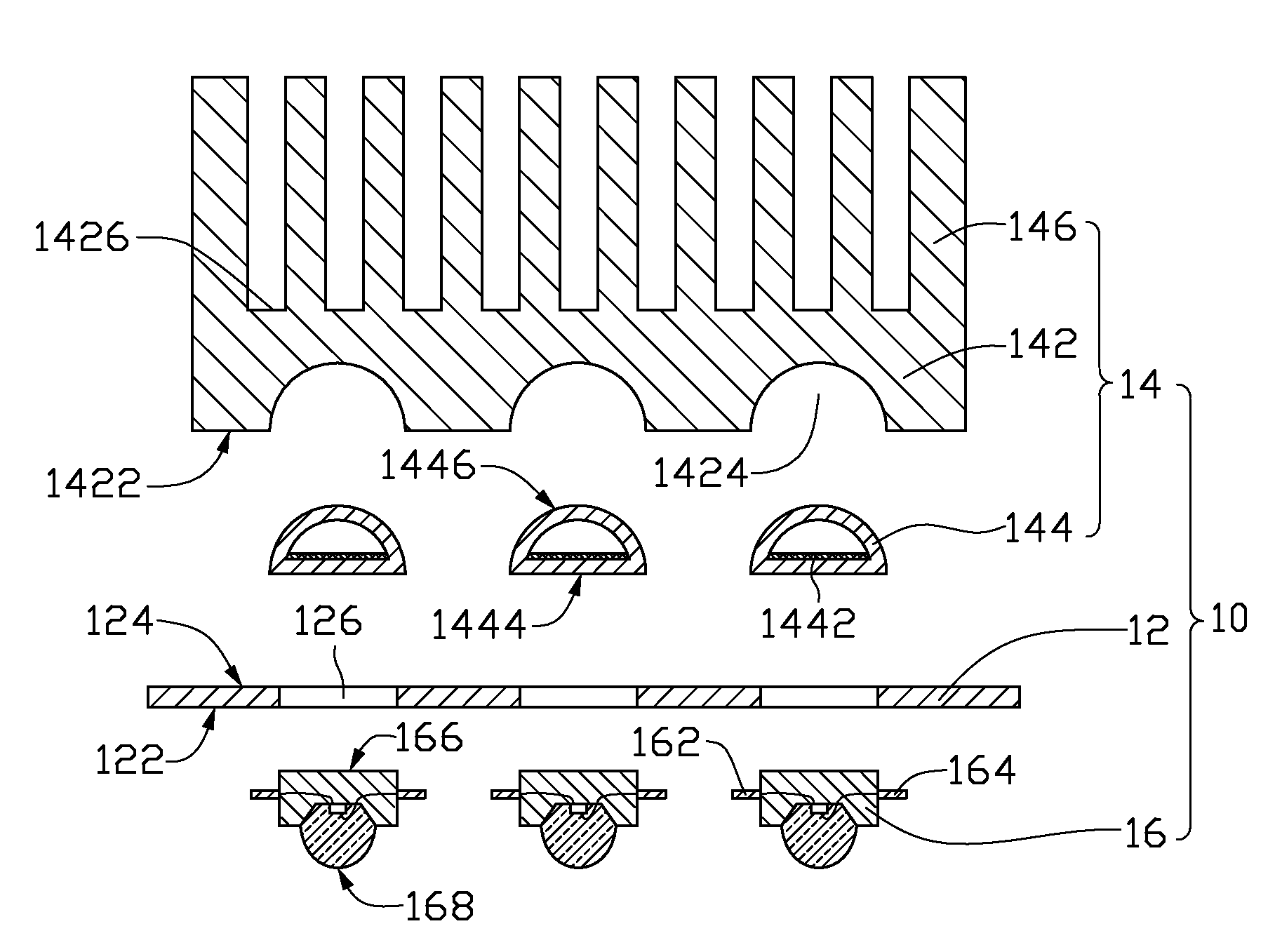
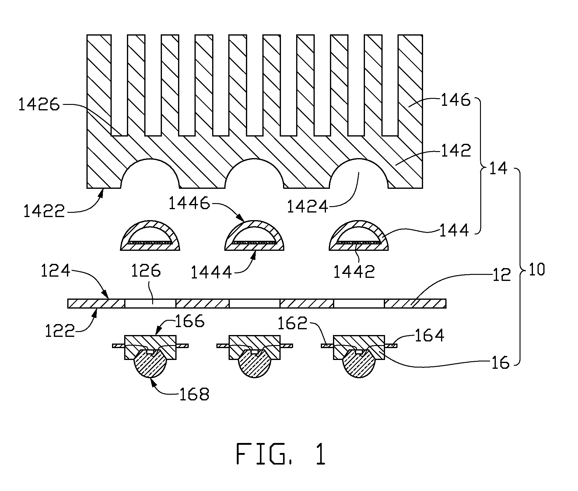
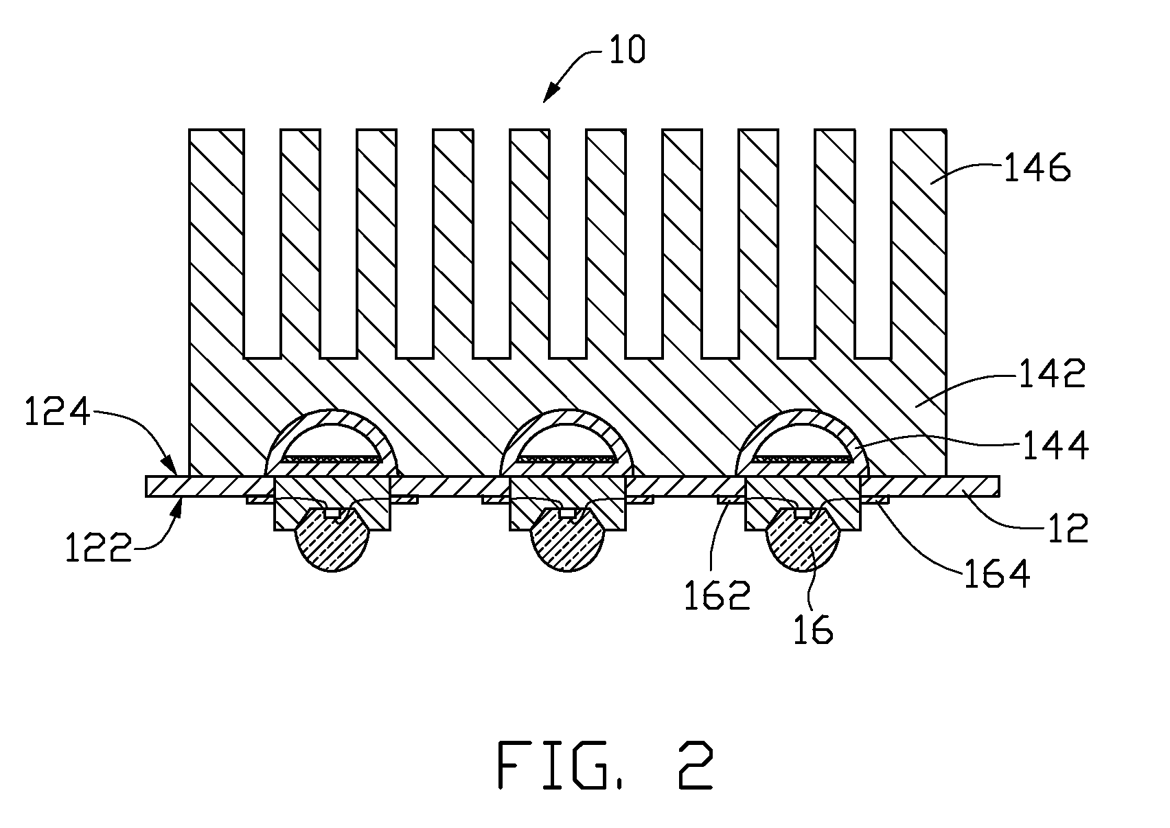
[0016]Referring to FIGS. 1 and 2, a light source module 10, in accordance with a present embodiment, is provided. The light source module 10 includes a printed circuit board 12, a heat-dissipating assembly 14, and a number of light emitting elements 16.

[0017]The printed circuit board 12 includes a first surface 122, a second surface 124 opposite to the first surface 122, and a number of through holes 126 penetrating / extending through the first and the second surfaces 122, 124. The first surface 122 generally is formed with a number of pads (not shown) thereon for facilitating the electrical connection with the light emitting elements 16. Generally, the number of the through holes 126 corresponds with the number of the light emitting elements 16. The printed circuit board 12 rather suitably is a glass-fiber board, a ceramic board, or a metal core printed circuit board (MCPCB).

[0018]The heat-dissipating assembly 14 is, usefully, located immediately adjacent to the second surface 124 t...


PUM


Abstract

An exemplary light source module includes a printed circuit board (PCB), a heat-dissipating assembly, and a number of light emitting elements. The PCB includes a first surface, an opposite second surface, and a number of through holes. The heat-dissipating assembly is located adjacent to the second surface and includes a base, a number of heat-conducting elements, and a number of heat dissipation fins. The base includes a third surface defining a number of cavities therein and an opposite fourth surface. The heat dissipation fins extend from the fourth surface. Each of the heat-conducting elements is inlaid in a corresponding cavity. Each of the light emitting elements is placed in a corresponding through hole and thermally contacts a corresponding heat-conducting element. Each light emitting element electrically connects with the PCB and defines a respective light emitting surface located outside the corresponding through hole.

Description

BACKGROUND[0001]1. Technical Field[0002]The present invention relates to light source modules and, particularly, to a light source module with a high heat-dissipation efficiency.[0003]2. Description of Related Art[0004]A light emitting diode (LED) is one type of semiconductor light source, and the electrical and optical characteristics and life span thereof are greatly temperature-dependent. Generally, a high working temperature will cause a deterioration of an internal quantum efficiency of the LED and shorten the life span thereof. Furthermore, a resistance of a semiconductor has a negative temperature coefficient and tends to be reduced with an increase in the working temperature. Such a reduced resistance will correspondingly result in a larger current at a given voltage and the generation of excessive heat. If the excessive heat cannot be effectively dissipated, a phenomenon of heat accumulation will be difficult to avoid, and, accordingly, the deterioration of the LED can be e...

Claims


Application Information

Patent Timeline
Patent Type & Authority Patents(United States)
IPC IPC(8): F21V29/00H01L23/34H05K7/20
CPCF21V29/004F21V29/006F21V29/763H05K7/205F21Y2101/02H05K1/0203H01L2924/0002H05K1/182H01L2924/00F21Y2115/10F21V29/51F21V29/74
Inventor SUN, CHIH-HSIENCHANG, CHENG-WEI
Owner FOXSEMICON INTEGRATED TECH INC
Why Eureka
Try Eureka