Thermal module and electronic assembly incorporating the same

a technology of electronic assembly and thermal module, which is applied in the direction of fluid heaters, lighting and heating apparatus, cooling/ventilation/heating modifications, etc., can solve the problems of generating air turbulence, reducing the heat dissipation efficiency of the thermal module, and blocking the flow towards the sidewall of the casing from the fin assembly, etc., to achieve high heat dissipation efficiency

Inactive Publication Date: 2008-06-26
HON HAI PRECISION IND CO LTD
View PDF14 Cites 29 Cited by
  • Summary
  • Abstract
  • Description
  • Claims
  • Application Information

AI Technical Summary

Benefits of technology

[0006]The present invention relates, in one respect, to a thermal module having a high heat dissipating efficiency. The thermal module includes a centrifugal blower, a fin assembly and a plurality of sub-fins. The centrifugal blower has a bottom housing defining an air outlet therein. The fin assembly is disposed at the air outlet of the centrifugal blower and has a plurality of fins forming a plurality of air passages therebetween. The sub-fins are integrally formed with the bottom housing of the centrifugal blower from a single piece. Each of the sub-fins has an inner side connecting with a corresponding fin of the fin assembly and an outer side distant from the fin assembly. A plurality of air channels are formed between adjacent sub-fins and communicate with the air passages of the fin assembly.

Problems solved by technology

However, as density of the barriers of the casing is smaller than the density of the fins of the fin assembly and a thickness of each of the barriers of the casing is greater than the thickness of each of the fins of the fin assembly, some part of the air flowing towards the sidewall of the casing from the fin assembly is blocked by the barriers of the casing when the fin assembly is located adjacent to the sidewall of the casing.
The blockage of the air by the barriers decreases the heat dissipating efficiency of the thermal module.
However, different parts of the airflow mix with each other and therefore generating air turbulence in a space formed between the fin assembly and the sidewall of the casing.
The air turbulence decreases flow speed of the airflow and further decreases the heat dissipating efficiency of the thermal module.

Method used


Image

  • Thermal module and electronic assembly incorporating the same
  • Thermal module and electronic assembly incorporating the same
  • Thermal module and electronic assembly incorporating the same

Examples


Embodiment Construction

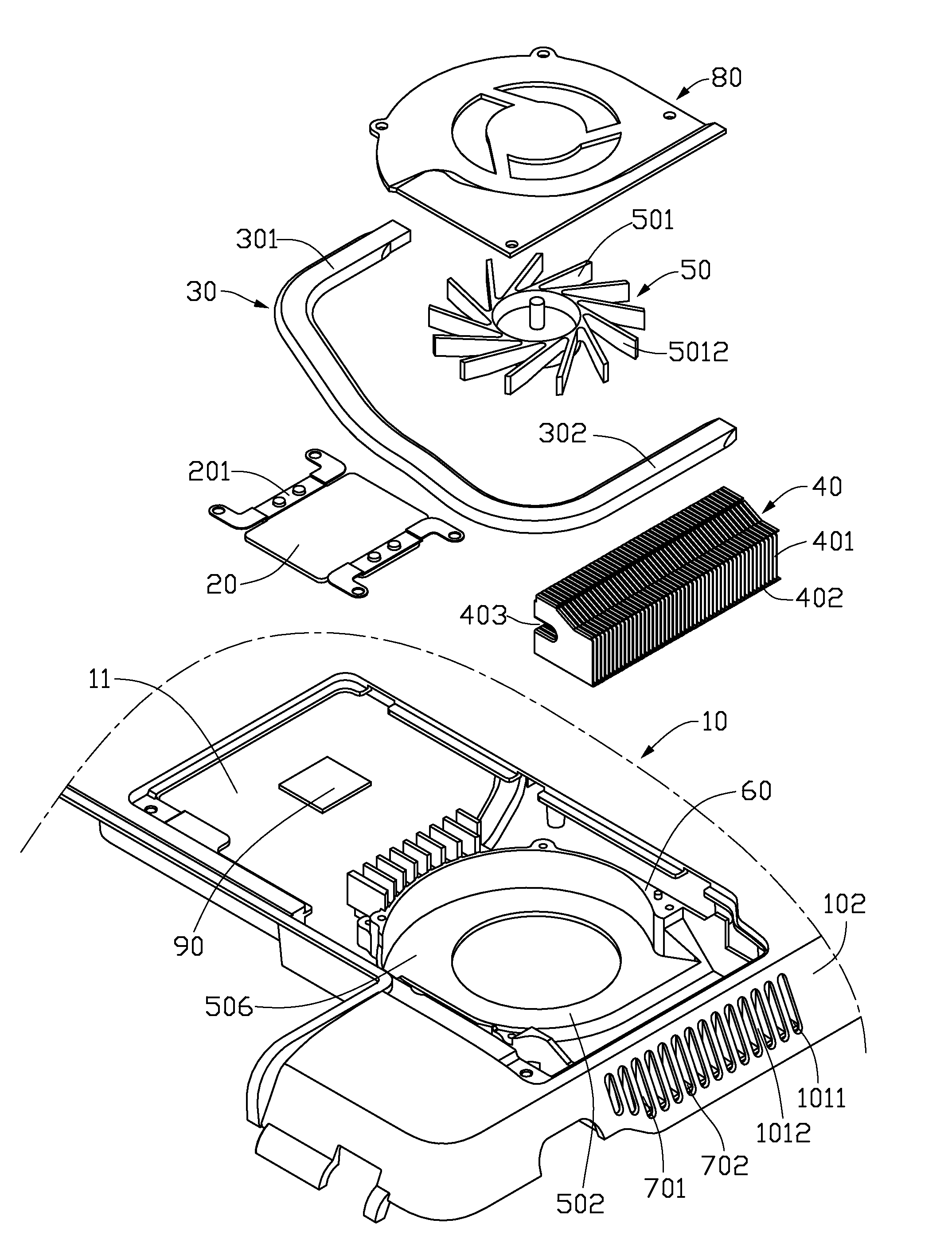
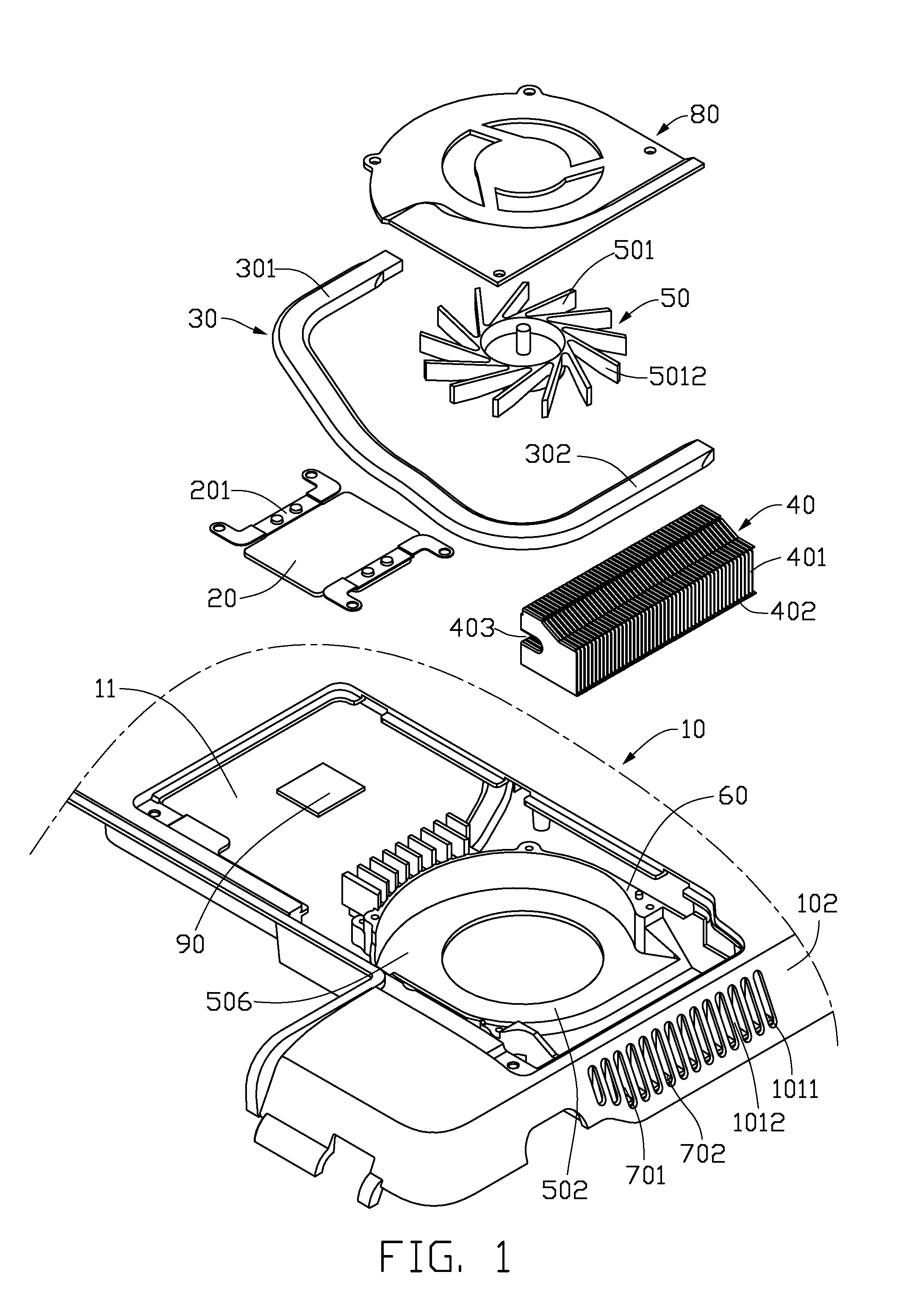
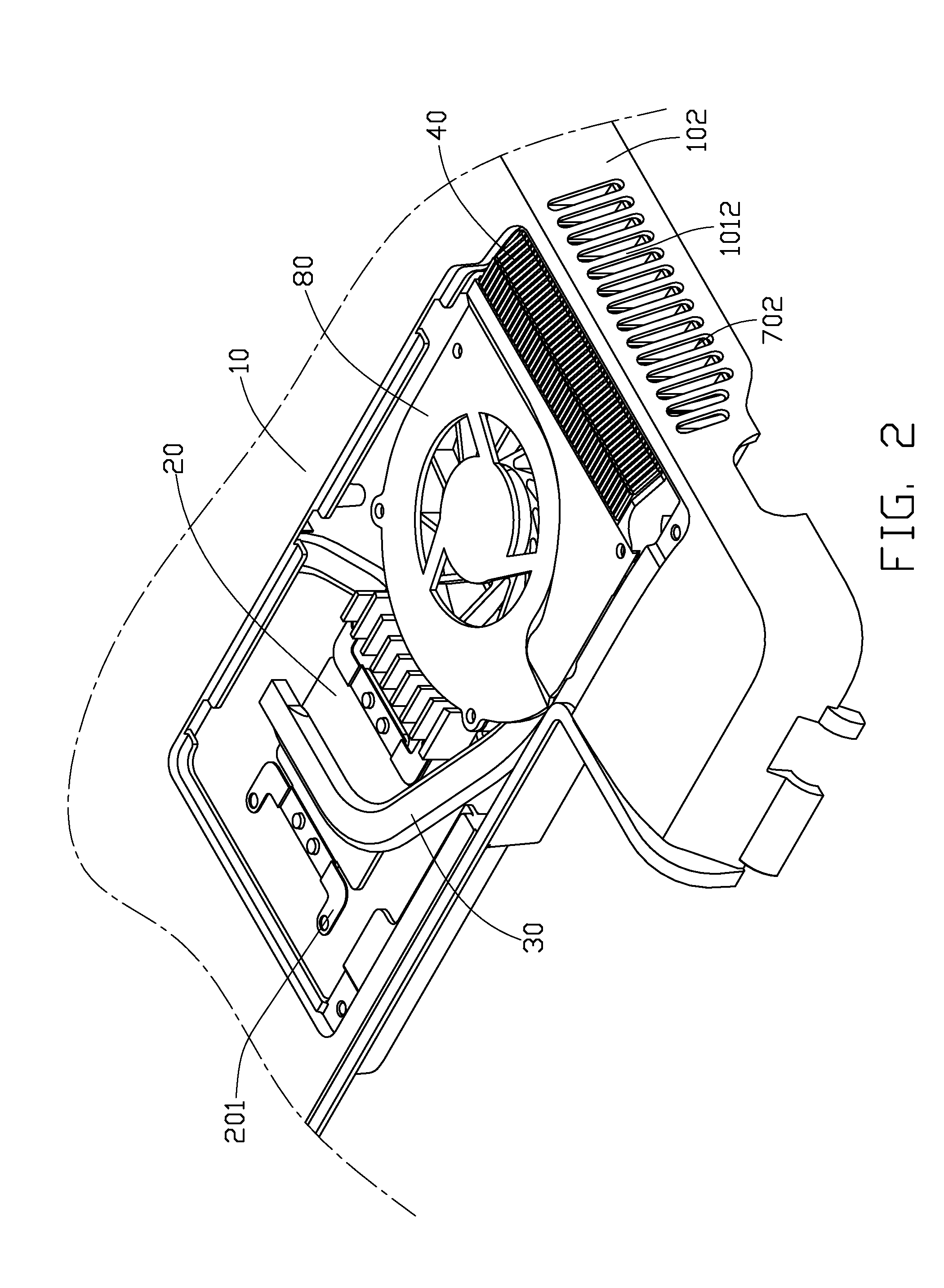
[0017]Referring to FIGS. 1 and 2, an electronic assembly according to a preferred embodiment of the present invention is shown. The electronic assembly includes a portable electronic product having a casing 10 and a thermal module mounted in the casing 10. The portable electronic product may be a laptop computer, or a DVD player. The thermal module includes a heat spreader 20, a flattened heat pipe 30, a centrifugal blower 50 and a fin assembly 40.

[0018]The heat spreader 20 is mounted on a heat generating electronic component 90 via two resilient clips 201. The heat pipe 30 has a C-shaped configuration, and has an evaporation section 301 thermally connecting with the heat spreader 20 and a condensation section 302 thermally connecting with the fin assembly 40 to transfer heat therebetween.

[0019]The centrifugal blower 50 includes a bottom housing 60, a top lid 80 covering the bottom housing 60, a stator (not shown) disposed in a space cooperatively enclosed by the bottom housing 60 a...


PUM


Abstract

An electronic assembly includes a casing (10) of an electronic product, and a thermal module disposed in the casing. The casing has a sidewall (102) defining a plurality of slots (1011) therein. The thermal module includes a centrifugal blower (50), a fin assembly (40) and a plurality of sub-fins (701). The centrifugal blower defines an air outlet (502) therein. The fin assembly is disposed at the air outlet of the centrifugal blower and includes a plurality of fins (401) and has a plurality of air passages (402) formed between adjacent fins. The sub-fins are located between the fin assembly and the sidewall of the casing, and forming a plurality of air channels (702) therebetween. The air channels of the sub-fins communicate the air passages of the fin assembly with the slots of the sidewall of the casing.

Description

BACKGROUND OF THE INVENTION[0001]1. Field of the Invention[0002]The present invention relates to thermal module, and more particularly to a thermal module having high heat dissipating efficiency and an electronic assembly incorporating the thermal module.[0003]2. Description of Related Art[0004]Thermal modules are traditionally used in micro-electronics to help transfer heat from heat generating electronic components of the micro-electronics. The thermal module is mounted to a casing of the micro-electronics and includes a centrifugal blower, a fin assembly disposed at an air outlet of the centrifugal blower, a heat pipe thermally connecting the heat generating electronic component with the fin assembly to transfer heat therebetween. In operation of the thermal module, the centrifugal blower generates airflow flowing through the fin assembly to take away heat therefrom.[0005]In the micro-electronics, the fin assembly is located adjacent to a sidewall of the casing of the micro-elect...

Claims


Application Information

Patent Timeline
Patent Type & Authority Applications(United States)
IPC IPC(8): H05K7/20
CPCH05K7/20154
Inventor LIANG, SHANG-CHIHHUNG, JUI-WEN
Owner HON HAI PRECISION IND CO LTD
Why Eureka
Try Eureka