Double-handled clipboard

a clipboard and double-handled technology, applied in the field of flat boards, can solve the problem that the thumb cannot fit in the thumb hole, and achieve the effect of facilitating the gripping of the clipboard

a clipboard and double-handled technology, applied in the field of flat boards, can solve the problem that the thumb cannot fit in the thumb hole, and achieve the effect of facilitating the gripping of the clipboard

US20060237621A1Inactive Publication Date: 2006-10-26WOLFF MEDICAL MARKETING & DESIGN

Image

  • Double-handled clipboard
  • Double-handled clipboard

Examples


Embodiment Construction

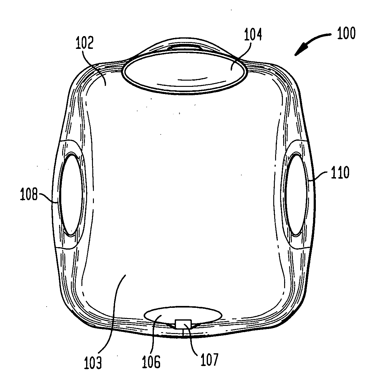
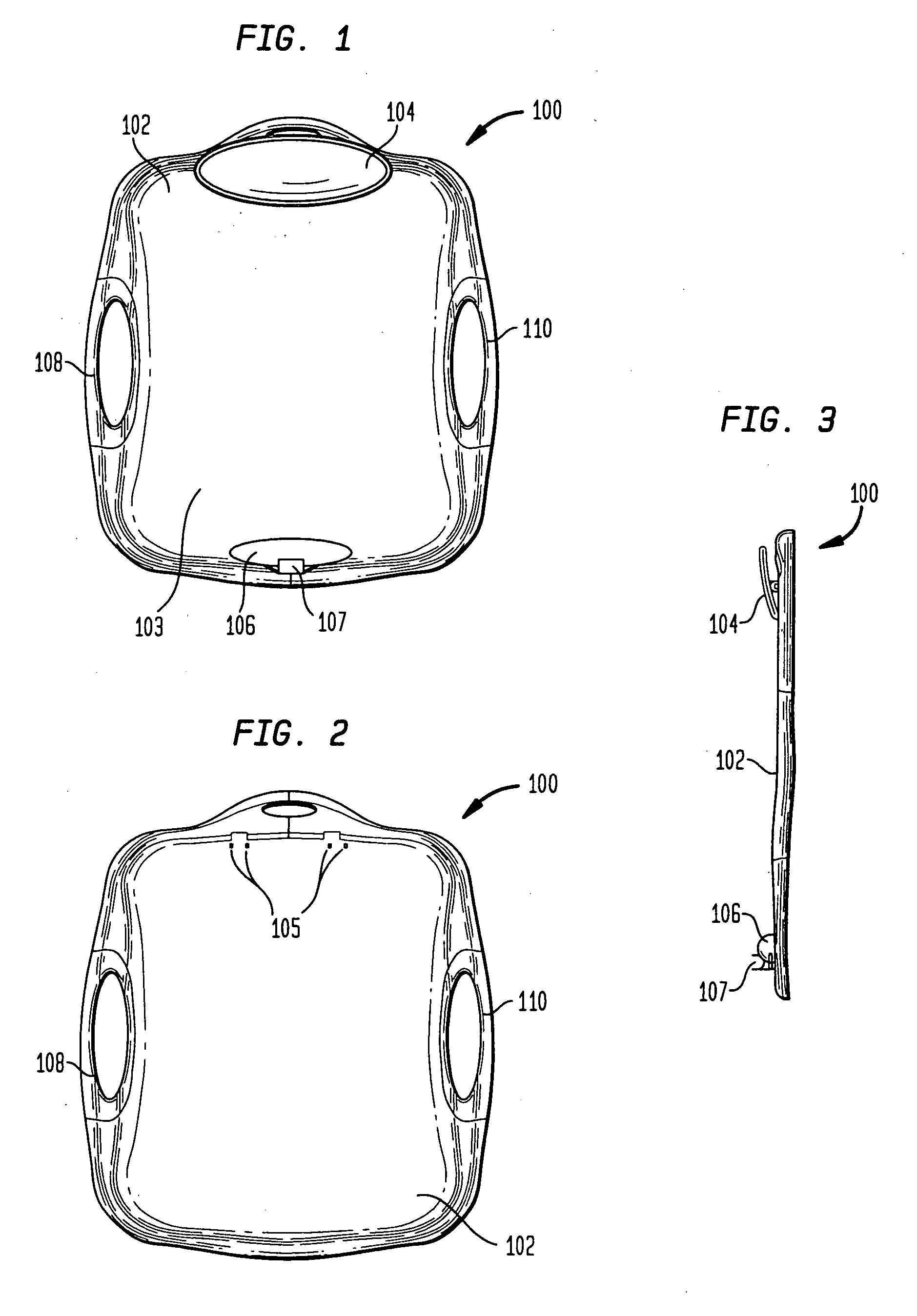
[0032] Referring to FIG. 1, the clipboard is generally designated as 100 in accordance with a preferred embodiment of the present invention. In this embodiment, the clipboard 100 is substantially a flat rectangular board 102 with contoured side edges and a paperclip 104 is disposed at the top of the board 102.

[0033] Referring to FIGS. 2 and 3, the paperclip 104 in this embodiment is attached by engaging integrally formed tabs 105 with corresponding tabs on a clip structure that includes a spring. The integrally formed corresponding tabs 105 enable the paperclip 104 to be securely attached to board 100. Any suitable means of attachment may be used to attach or hold the clip to the board, including adhesive, magnets, magnetic substrate materials such as strips or buttons, etc, as will be discussed further below.

[0034] Contoured side edges in the preferred embodiment are raised and rounded about the periphery of the board. The edges contoured with a radius about the periphery, leavin...


PUM


Abstract

The present invention can be practiced as a clipboard that has a flat rectangular board with contoured side edges containing an element for holding papers or other thin items and two indented apertures for holding the board with four fingers. The surface of the clipboard may be magnetic, contain magnetic strips or buttons, a dry erase board, or a combination of the surfaces mentioned. Each aperture may be located on opposite or adjoining side edges and is surrounded by a rubber gripping surface to facilitate gripping and comfort. The clipboard also may include a second paperclip for securing papers or other thin items and a pen clamp for securing pens, dry erase markers, or other writing utensils at the bottom of the board.

Description

CROSS-REFERENCE TO RELATED APPLICATIONS [0001] This application is a continuation-in-part of an application entitled “Double-Handled Clipboard” filed on Apr. 22, 2005, which is a continuation of U.S. application Ser. No. 29 / 227,875, filed on Apr. 15, 2005, which is a continuation of U.S. application Ser. No. 29 / 218,504, filed on Dec. 3, 2004, the disclosures of which are hereby incorporated herein by reference.BACKGROUND OF THE INVENTION [0002] The present invention relates to a flat board with openings that serve as handles. [0003] Clipboards have applicability in a variety of activities in any industry and in connection with educational purposes. Typically, clipboards are held around an edge when being carried or used. A clipboard in U.S. Pat. No. 4,586,730 includes two thumb holes for the left and right thumbs that allow a person to hold the clipboard while writing. The thumb extends from below the board and is pressed against the front surface of the board while writing. A hand ...

Claims


Application Information

Patent Timeline
26 Oct 2006
Publication
US20060237621A1
IPC
A47B97/04
CPC
B42F9/001
Inventors
WOLFF, STEPHEN H.; JONES, AUBREY