Chair for spinal deceases prevention and treatment

a spinal deceases and chair technology, applied in the field of chair for spinal deceases prevention and treatment, can solve the problem that the devices mentioned above do not provide any therapeutic effects

Inactive Publication Date: 2006-10-26
BARANOV MICHAEL V +2
View PDF13 Cites 11 Cited by
  • Summary
  • Abstract
  • Description
  • Claims
  • Application Information

AI Technical Summary

Benefits of technology

The invention described in this patent makes chairs that can be folded up easily, making them more versatile because they can be used at different locations like homes, worksites, or even places where people relax.

Problems solved by technology

This patent describes an issue with spinal disease that has become more common due to a sedentary life style. Current devices on the market only work to strengthen muscles but don’t offer much therapy for spinal issues like those involving the lumbar region. Therefore, this new invention focuses on developing a device that can target specific muscles and cords near the spine to prevent or treat these conditions.

Method used


Image

  • Chair for spinal deceases prevention and treatment
  • Chair for spinal deceases prevention and treatment
  • Chair for spinal deceases prevention and treatment

Examples


Embodiment Construction

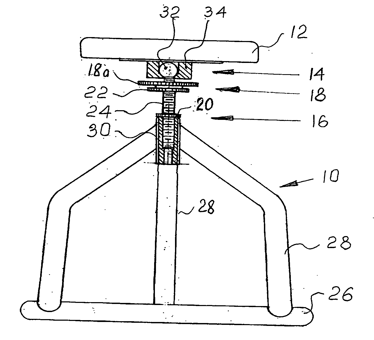
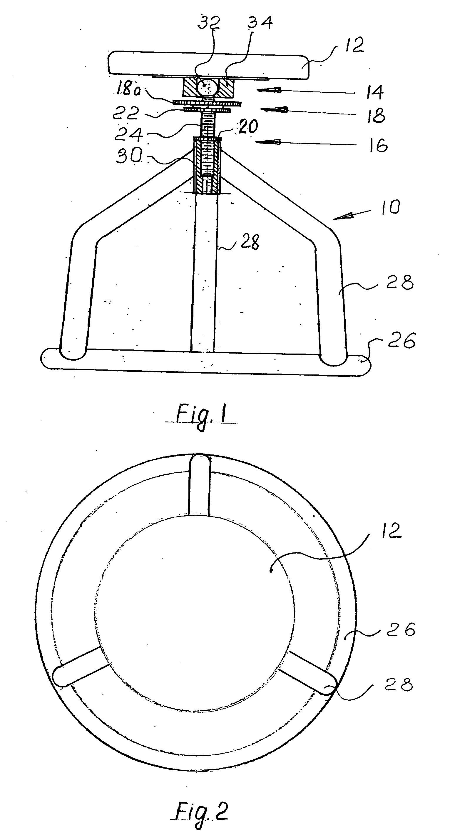
[0035]FIG. 1, 2 show one of the preferable embodiments of the offered invention. According to it; the chair includes a base (10), a seat (12) connected with said base, a device (14) for a turning of said seat in horizontal flatness and inclining in vertical flatness. In addition, the chair is equipped with a device (16) for seat height regulation and a device (18) for seat incline (swing amplitude) regulation.

[0036] According to this version (FIG. 1, 2) the base includes a ring (26) made, for example, of pipe billet or any other similar material. No less than three connections (28) are attached to the ring (26) in the form of pipes or bars, in equal distances from each other along the ring (26). Spare ends of the connections (28) are attached to a sleeve (30). Said sleeve has internal thread linked with a screw (24), which is connected with the seat (12) by a ball-and-socket join (14). A ball part (32) of this join (14) is attached to the screw (24) and is placed into a socket part...


PUM


Abstract

A chair is intended to serve in the health-improvement medicinal field and refers to the training devices for spinal diseases prevention and treatment. The present chair includes a base, a seat, connected with said base, a device for turning of said seat in horizontal flatness and inclining in vertical flatness. Besides, the chair includes the device for the seat height regulation and the device for seat incline (swing amplitude) regulation in vertical flatness. The chair has additional device for turn-over the seat, which allows folding this chair in a portable position and to wide a possible sphere of usage (places of work or places of rest).

Description


Claims


Application Information

Patent Timeline
Owner BARANOV MICHAEL V
Why Eureka
Try Eureka