Imaging and eccentric atherosclerotic material laser remodeling and/or ablation catheter

a laser remodeling and atherosclerotic material technology, applied in the field of medical devices, systems and methods, can solve the problems of invasive bypass surgery, increased risk of major surgical complications, and limited blood flow,

Inactive Publication Date: 2005-11-10
VESSIX VASCULAR
View PDF99 Cites 504 Cited by
  • Summary
  • Abstract
  • Description
  • Claims
  • Application Information

AI Technical Summary

Benefits of technology

[0015] The present invention generally provides improved devices, systems, and methods for treating atherosclerotic lesions and other disease states. While also being well-suited for treatment of occlusive diseases, the techniques of the present invention are particularly advantageous for treatment of patients who have (or are at risk of having) vulnerable plaques, regardless of whether those vulnerable plaques cause significant occlusion of an associated vessel lumen. Catheter systems of the present invention can incorporate optical coherence tomography or other imaging techniques which allow a structure and location of an eccentric plaque to be characterized. Ablative laser energy can then be selectively and automatically directed to the appropriate plaque structures, often without imposing mechanical trauma to the entire circumference of the lumen wall generally associated with balloon dilation, stenting, and known atherectomy methods.

Problems solved by technology

As a result, blood flow is restricted and there is an increased likelihood of clot formation that can partially or completely block or occlude an artery, often causing a heart attack.
Invasive bypass surgery can involve prolonged hospitalization and an extensive recuperation period, as well as the risk of major surgical complications.
Although they can remove some plaque from coronary arteries, existing atherectomy devices may be less effective in treating certain types of lesions.
For example, rotational atherectomy may be less effective in the treatment of softer atherosclerotic materials such as vulnerable plaques.
Every year, the narrowing was thought to grow more severe until one day no blood can get through and the patient has a heart attack.
Instead, heart attacks may often occur when an area of vulnerable plaque bursts, a clot forms over the area and blood flow is abruptly blocked.
In a large percentage of cases, the plaque that erupts was not obstructing an artery sufficiently target the plaque for stenting or a bypass.
This dangerous vulnerable plaque is often soft and fragile, may produce no symptoms, and would not necessarily be seen as an obstruction to blood flow.
This may be why so many heart attacks are unexpected—a person will be out jogging one day, feeling fine, and may be struck with a heart attack the next.
If a narrowed artery were the culprit, exercise might have caused severe chest pain.
The laser energy emerging from a small number of fibers bundled together may produce small openings, and do not always remove an adequate quantity of matter from the lesion for use as a sole (or even primary) treatment.
As such drugs end up distributed throughout the patient's tissues they often have deleterious side effects, and they may not produce the desired results in a timely manner for at least some patients.

Method used


Image

  • Imaging and eccentric atherosclerotic material laser remodeling and/or ablation catheter
  • Imaging and eccentric atherosclerotic material laser remodeling and/or ablation catheter
  • Imaging and eccentric atherosclerotic material laser remodeling and/or ablation catheter

Examples


embodiment 110

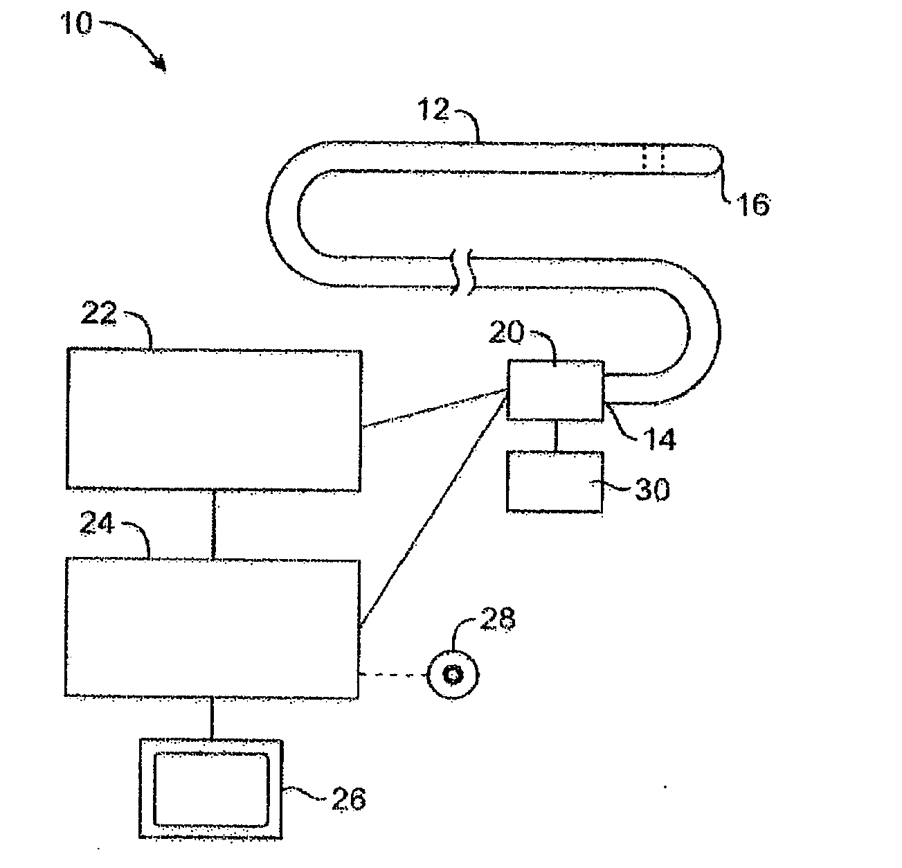
[0113] A preferred embodiment 110 can be understood with reference to FIG. 8. In this preferred embodiment, the same optical conduit or bundle of optical conduits 102 is used to convey the light energy for imaging, say imaging light 112, and the light energy for ablating atherosclerotic plaques, say remodeling and / or ablating light 114. The optical conduits are housed inside a sleeve catheter or guidewire 104.

[0114] As can be understood with reference to FIGS. 8, 9A-9D, and 10A-10D, the optical conduits rotate continuously inside the sleeve catheter. The imaging light runs through the optical conduits and radially through transparent cylindrical windows 122 to provide an intra-vascular image of artery 116, for instance by OCT. The image is processed by a computer that identifies and localizes atherosclerotic plaques 118. Based on the information from the imaging, the computer then determines when to fire the ablating light 114 such that the light ablates specifically the plaque and ...

embodiment 120

[0115] A preferred embodiment 120 can be understood with reference to FIG. 11. Two different optical conduits or bundles of optical conduits, 102a and 102b, are used to convey the light energy for imaging, say imaging light 112, and the light energy for ablating and / or remodeling atherosclerotic plaques, say ablating light 114. The optical conduits are housed inside a sleeve catheter 104 or guidewire. As shown in FIG. 12, conduits 102a, 102b can rotate around a common longitudinal axis 124. The fold mirrors 108 are facing first and second radial directions, often being opposed directions.

[0116] Optical conduits 102a and 102b may rotate continuously inside sleeve catheter 104. The imaging light runs through optical conduit 102a and provides an intra-vascular image of the artery, for instance by OCT. The ablating light runs through conduit 102b. The imaging and ablating lights can be used sequentially or simultaneously. The image is processed by a computer that identifies and localize...

embodiment 130

[0117] Preferred embodiment 130 may be understood with reference to FIGS. 13-16F. Two different optical conduits or bundles of optical conduits 102a and 102b, are used to convey the light energy for imaging, say imaging light 112, and the light energy for remodeling and / or ablating atherosclerotic plaques, say ablating light 114. The optical conduits 102a, 102b are housed inside a sleeve catheter or guidewire. Conduits 102a and 102b again may rotate around a common longitudinal axis, with their associated lenses 106 and fold mirrors 108 may be being axially staggered or separated and their optical paths facing either the same or different directions, depending on the configuration. The illustration of FIGS. 14A-14D and 15A-15D show the optical paths facing the same direction, and the imaging light 112 and the ablating light 114 being used sequentially. The illustration of FIG. 16 shows a different configuration: the imaging and optical paths face different, generally opposed directi...


PUM


Abstract

Devices, systems, and methods for treating atherosclerotic lesions and other disease states, particularly for treatment of vulnerable plaques, can incorporate optical coherence tomography or other imaging techniques which allow a structure and location of an eccentric plaque to be characterized. Remodeling and/or ablative laser energy can then be selectively and automatically directed to the appropriate plaque structures, often without imposing mechanical trauma to the entire circumference of the lumen wall.

Description

CROSS-REFERENCES TO RELATED APPLICATIONS [0001] This application claims the benefit of priority from U.S. Provisional Application No. 60 / 568,510, filed on May 5, 2004 and entitled “Imaging and Eccentric Atherosclerotic Material Laser Ablation Catheter,” the full disclosure of which is incorporated herein by reference. [0002] The subject matter of the present application is related to that of U.S. Provisional Application No. 60 / 502,515, filed on Sep. 12, 2003 for “Selectable Eccentric Ablation of Atherosclerotic Material” (Atty. Docket No. 21830-000100US); and to that of U.S. application Ser. No. 10 / 938,138, filed on Sep. 10, 2004 and entitled “Selectable Eccentric Remodeling and / or Ablation of Atherosclerotic Material,” the full disclosures of which are also incorporated herein by reference.STATEMENT AS TO RIGHTS TO INVENTIONS MADE UNDER FEDERALLY SPONSORED RESEARCH OR DEVELOPMENT [0003] NOT APPLICABLE REFERENCE TO A “SEQUENCE LISTING,” A TABLE, OR A COMPUTER PROGRAM LISTING APPENDI...

Claims


Application Information

Patent Timeline
Patent Type & Authority Applications(United States)
IPC IPC(8): A61B5/00A61B18/00A61B18/20A61B18/22A61B18/24A61B19/00
CPCA61B5/0066A61B5/0075A61B5/0084A61B5/0086A61B2019/5231A61B18/245A61B2018/00982A61B2018/2272A61B5/6852A61B2090/373
Inventor STEINKE, TOM A.STONE, CORBETT W.MICHEL, RAPHAEL M.
Owner VESSIX VASCULAR
Why Eureka
Try Eureka