
Collimation assembly with an adjustment bracket capable of flexing when receiving a light source

a technology of light source and adjustment bracket, which is applied in the field of collimation assembly with an adjustment bracket capable of flexing when receiving a light source, can solve the problem of difficult to achieve accurate axial adjustment of the position of the holder relative to the mount member

Active Publication Date: 2006-10-26
LEXMARK INT INC
View PDF9 Cites 11 Cited by
  • Summary
  • Abstract
  • Description
  • Claims
  • Application Information

AI Technical Summary

Benefits of technology

[0006] The outer diameter of the holder may vary within a predefined first tolerance range while an inner diameter of the inner surface of the mount member may vary within a predefined second tolerance range. So as to maintain a light slip fit between the inner surface of the mount member and the holder for substantially any combination of parts falling within the first and second tolerance ranges, the mount member is provided with a hinge allowing it to flex as it receives the holder. Because the mount member is capable of flexing, one or both of the first and second tolerance ranges may be expanded beyond the ranges which would have been acceptable with a mount member without a hinge. Hence, the mount member with a hinge allows a light slip fit to be maintained between the holder and the mount member even if the outer diameter of the holder has a dimension at the upper limit of the first tolerance range and the inner diameter of the inner surface of the mount member has a dimension at the lower limit of the second tolerance range.

Problems solved by technology

Also, if the frictional engagement between the holder and the mount member is too great, accurate axial adjustment of the location of the holder relative to the mount member may be difficult to achieve.

Method used


Image

  • Collimation assembly with an adjustment bracket capable of flexing when receiving a light source
  • Collimation assembly with an adjustment bracket capable of flexing when receiving a light source
  • Collimation assembly with an adjustment bracket capable of flexing when receiving a light source

Examples


example

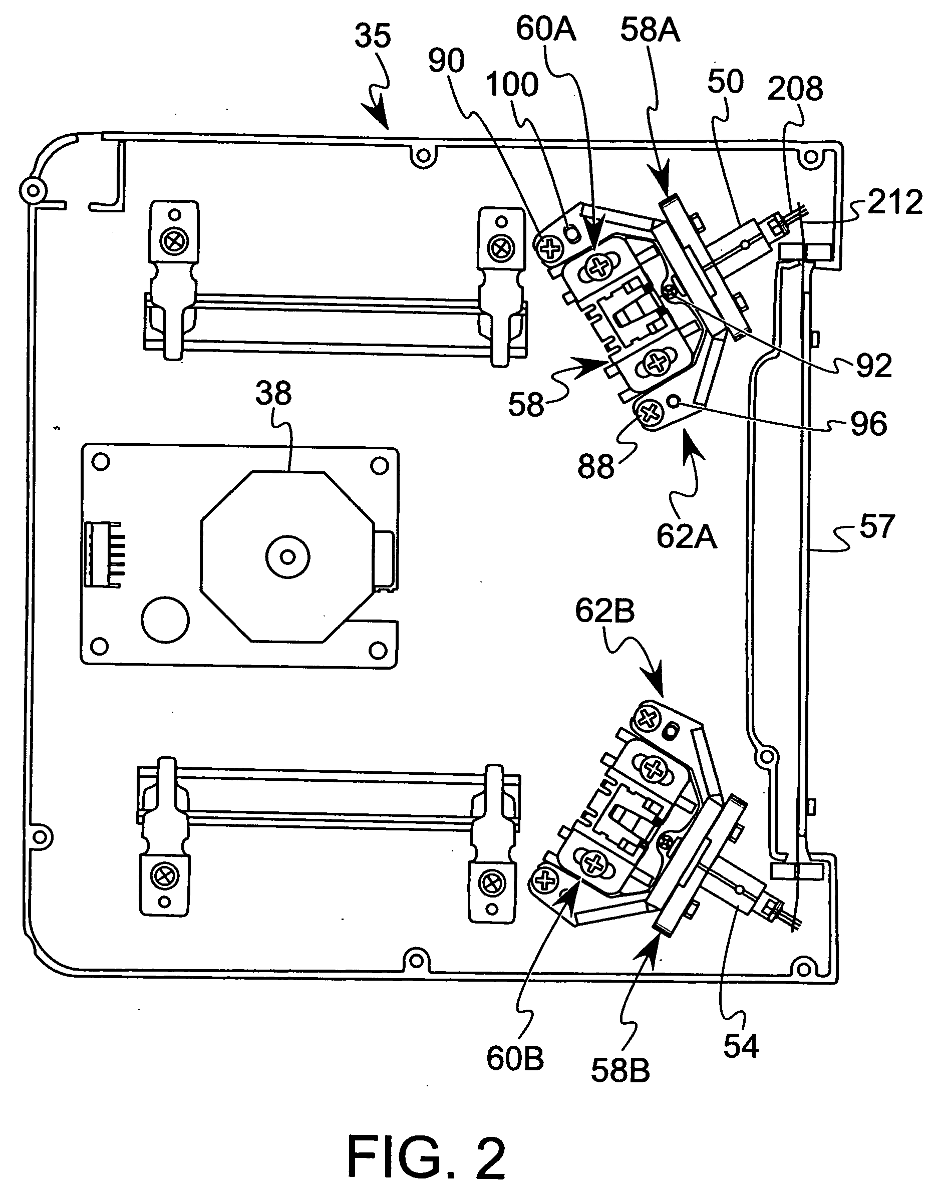
[0057] Adjustment brackets 66 formed from Noryl HM 4025 (Trademark) were provided, each having a mount member 136 with an outer diameter D of about 10 mm, a wall thickness of about 1.5 mm, and inner surface ribs 152, 154, 156 defining a cylindrical area 153 or inner surface portion having a diameter of about 6.360+0.015 mm. A plurality of light sources 50 were provided, each having a laser diode holder 158 formed from 6061 drawn seamless aluminum tube T6 temper. A first group of laser diode holders 158 had outer diameters which were greater than the diameter of the cylindrical area 153 by amounts equal to 10 microns, 20 microns, 30 microns, and 40 microns, respectively. Each of the first group laser diode holders were inserted into mount members not including a flex hinge. A first plot provided in FIG. 12 illustrates the force required for inserting each of the laser diode holders from the first group into mount members having a cylindrical area 153 with a diameter equal to 6.360 mm...


PUM


Abstract

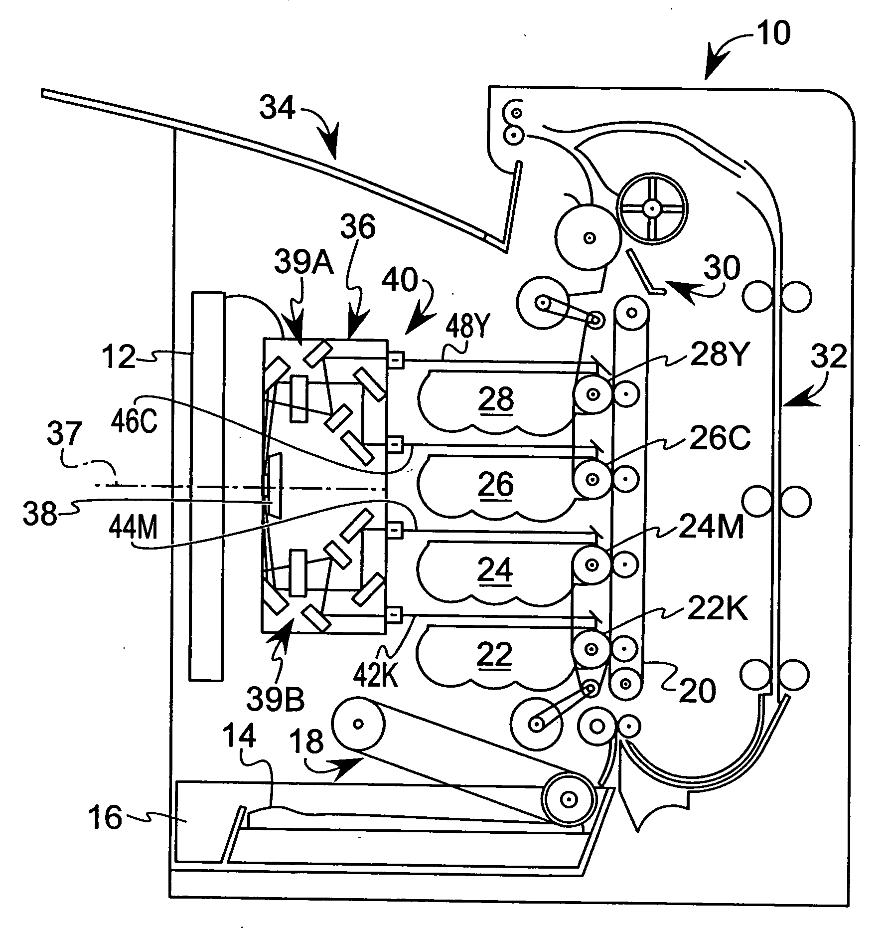
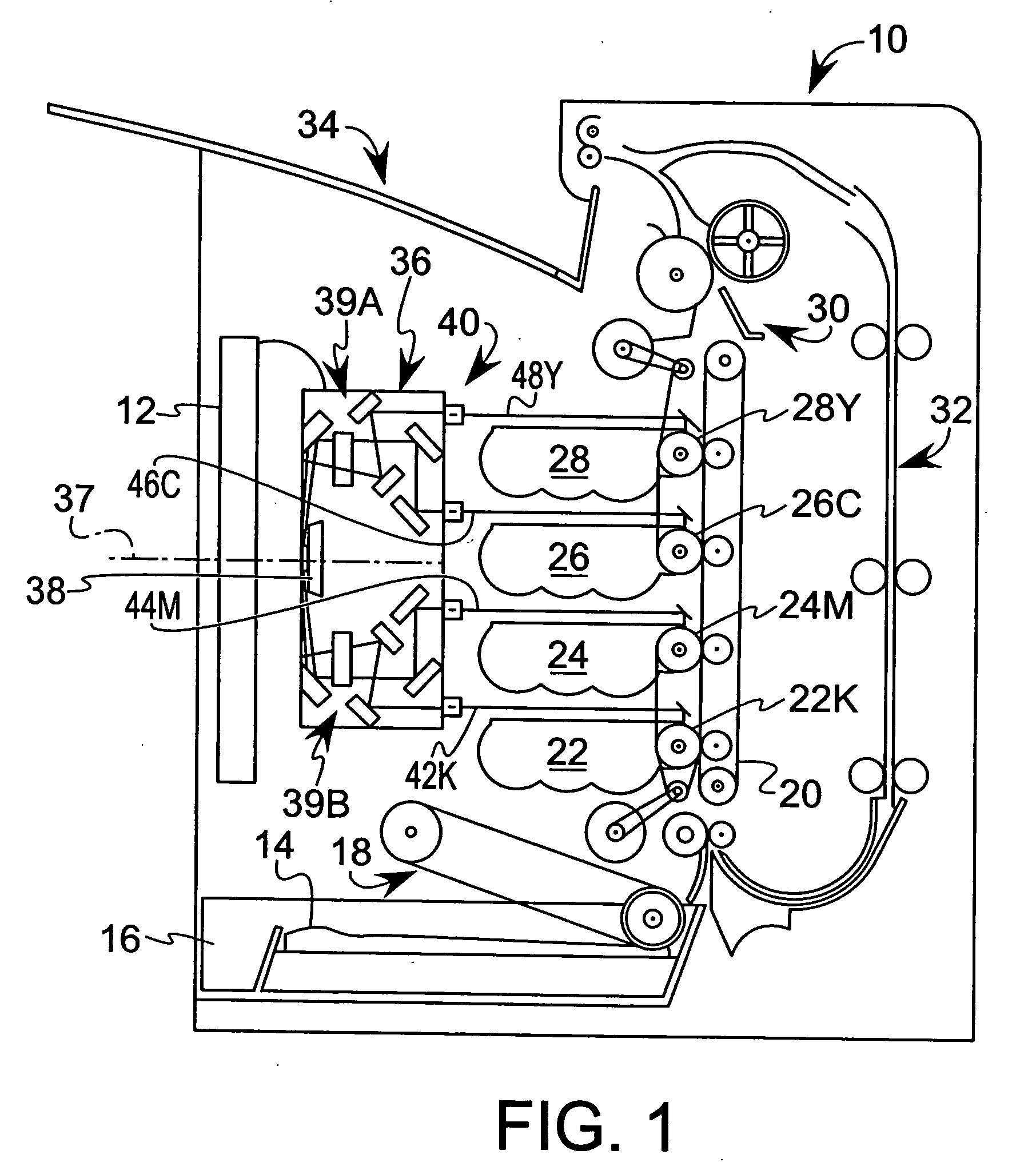
A collimation assembly is associated with a printhead housing for generating a substantially collimated laser beam. The collimation assembly comprises: a collimation housing mounted to the printhead housing to support a collimation lens; an adjustment bracket positioned adjacent the collimation housing; and a light source generating a light beam. The adjustment bracket comprises a mount member for receiving the light source such that the light beam is directed toward the collimation lens. The mount member may include first and second sections and a hinge defined between the first and second sections so as to allow the mount member to flex when receiving the light source.

Description

BACKGROUND OF THE INVENTION [0001] 1. Field of the Invention [0002] The present invention relates to an electrophotographic imaging apparatus, and more particularly, to a collimation assembly provided with an adjustment bracket capable of flexing to receive a light source. [0003] 2. Description of Related Prior Art [0004] Optical systems used in laser printers may be characterized as having three sub-systems or assemblies, namely, a laser diode / pre-scan optical assembly, a scanning assembly, and a post-scan assembly. Typically, the laser diode / pre-scan optical assembly includes a laser diode emitting a diverging laser beam, a collimation lens for collimating the beam emitted by the laser diode, and a pre-scan lens to focus the beam in a process direction prior to it striking the scanning device. During manufacturing, the distance between the collimation lens and the laser diode may be varied so as to focus the beam generated by the laser diode relative to the collimation lens. It wo...

Claims


Application Information

Patent Timeline
Patent Type & Authority Applications(United States)
IPC IPC(8): B41J2/45
CPCB41J2/473G02B7/004G02B26/124G03G15/0435G03G2215/0404G03G15/04072G03G15/326
Inventor DODDS, DANA ALLEN
Owner LEXMARK INT INC
Learn More