Low-Loss Polarized Light Diversion

a polarized light, low-loss technology, applied in the direction of instruments, catheters, optical radiation measurement, etc., can solve the problem that the sensing or forwarding probe may not accurately image the vessel or cavity wall, and achieve the effect of maintaining light polarization and minimal polarization loss

Active Publication Date: 2009-06-11
SPECTRANETICS
View PDF15 Cites 8 Cited by
  • Summary
  • Abstract
  • Description
  • Claims
  • Application Information

AI Technical Summary

Benefits of technology

[0007]Embodiments of the present invention provide for an optical sensor that provides lateral viewing while maintaining light polarization. This sensor may be used in various industrial and medical applications, such as PS-OCT catheter applications and non destructive testing applications. The sensor provides lateral viewing with minimal polarization loss. Such a sensor may be used in RF ablation, laser catheter ablation, catheters, stent placement, endoscopic applications, as well as industrial non-destructive testing applications.

Problems solved by technology

As such, probes or sensors with forward sensing or forwarding probing may not accurately image the vessel or cavity wall.

Method used


Image

  • Low-Loss Polarized Light Diversion
  • Low-Loss Polarized Light Diversion
  • Low-Loss Polarized Light Diversion

Examples


Embodiment Construction

[0024]The ensuing description provides preferred exemplary embodiment(s) only, and is not intended to limit the scope, applicability or configuration of the disclosure. Rather, the ensuing description of the preferred exemplary embodiment(s) will provide those skilled in the art with an enabling description for implementing a preferred exemplary embodiment. It being understood that various changes may be made in the function and arrangement of elements without departing from the spirit and scope as set forth in the appended claims.

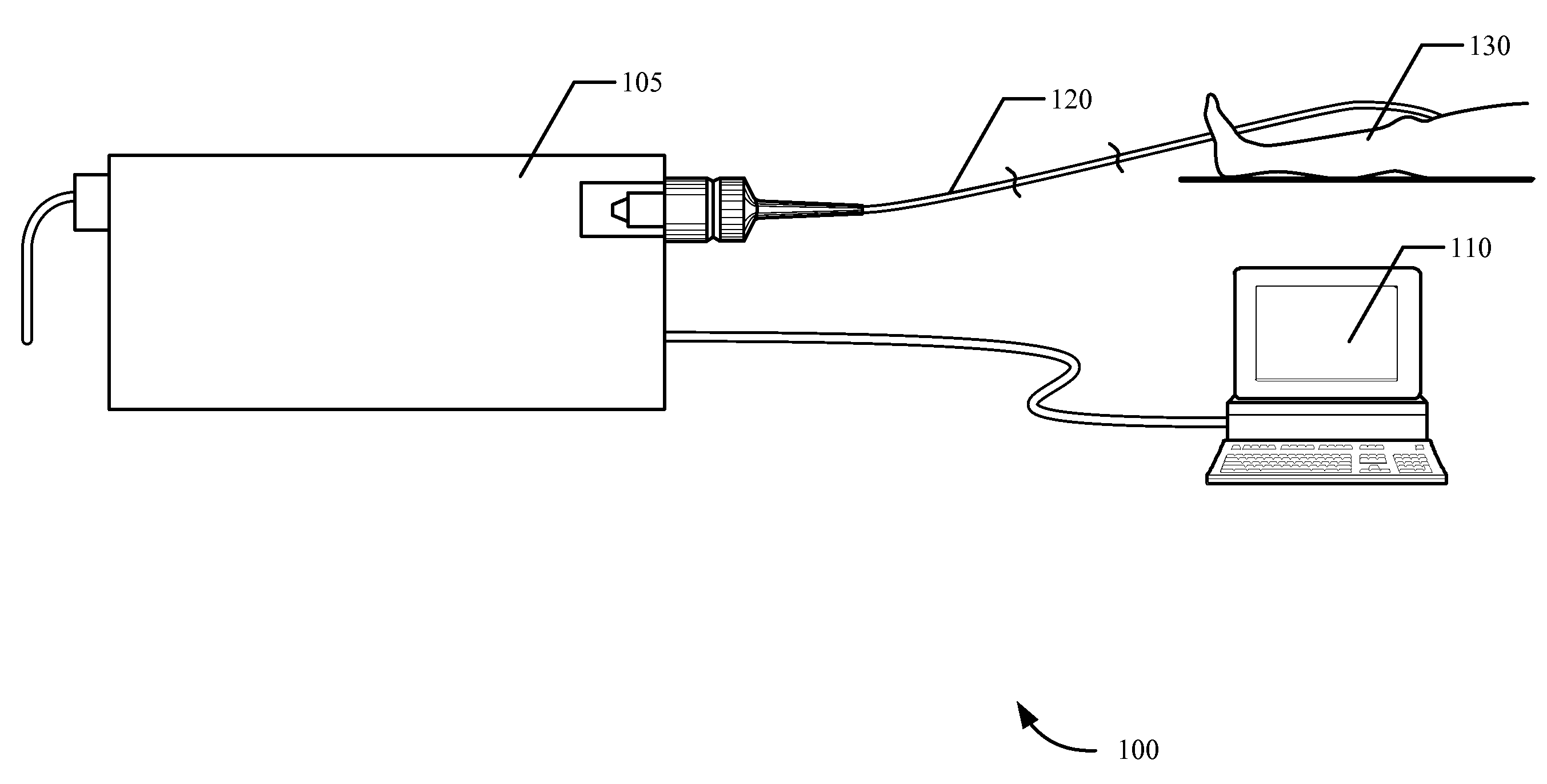
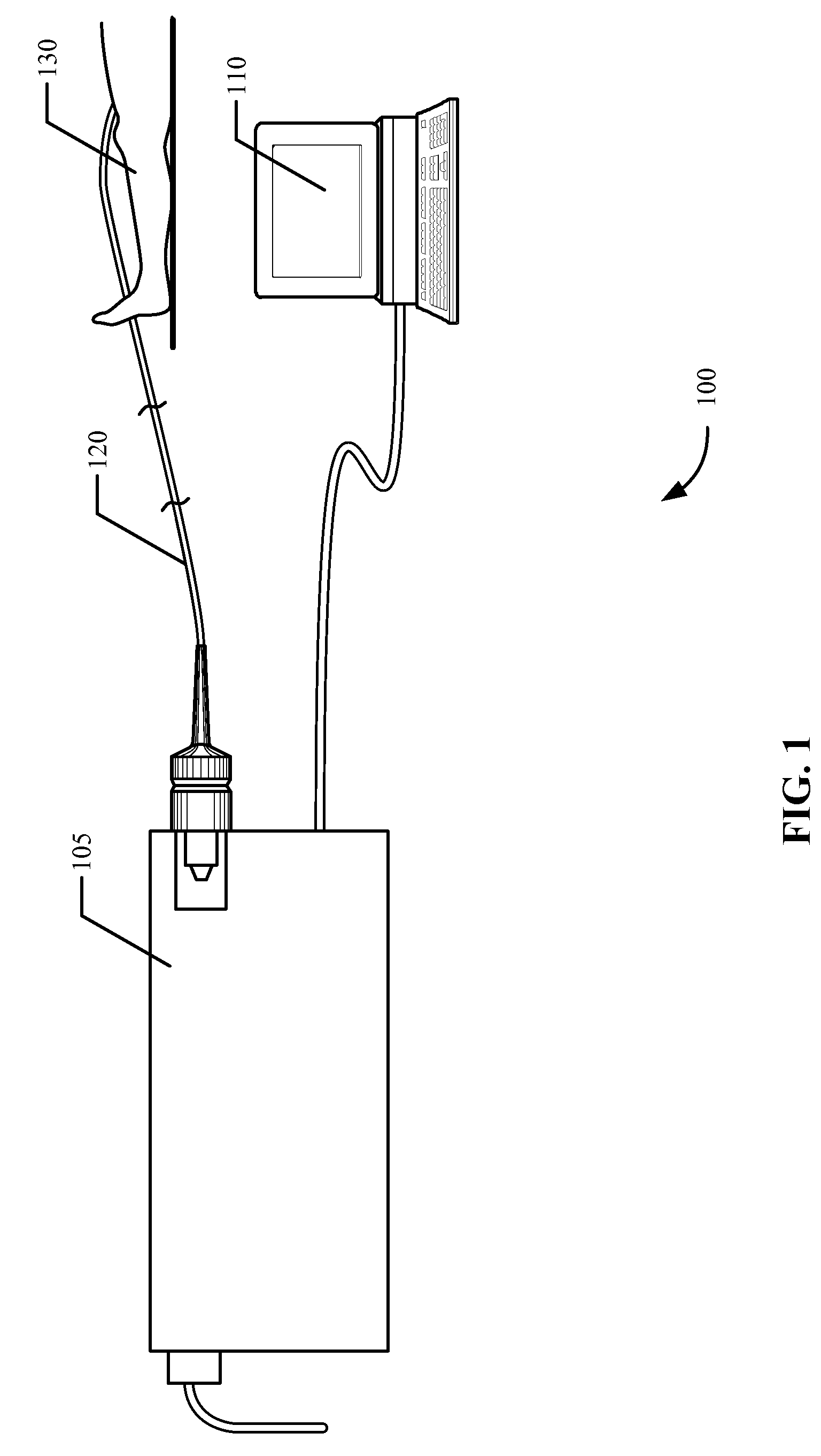
[0025]An optical sensor that provides lateral viewing while maintaining light polarization is provided according to one embodiment of the invention. The sensor may be used, for example, by a physician to monitor nearby tissue while removing a lead from an implanted electrical device such as a lead from a pace maker. Over time an implanted lead may become embedded within the surrounding tissue. Often such leads are removed using a catheter with a hollow inn...


PUM


Abstract

An optical sensor that provides lateral viewing while maintaining light polarization is disclosed according to one embodiment of the invention. The sensor includes a sensor body, at least one waveguide and at least one refractive optical element. The sensor body may includes proximal end and a distal end. The waveguide includes a proximal end coincident near the proximal end of the sensor body and a distal end coincident at a point near the distal end of the sensor body. The waveguide may include one or more fiber optic. The waveguide may be positioned within the sensor body. The refractive optical element may be positioned within the sensor near the distal end of the waveguide and may be configured to refract light received from the distal end of the waveguide outward from the sensor. The refractive optical element may include one or more prisms.

Description

BACKGROUND[0001]This disclosure relates in general to polarization sensitive sensors and, but not by way of limitation, to lateral viewing and polarization maintaining sensing devices amongst other things.[0002]Tissue birefringence can be used as a diagnostic tool for tissue state, such as damage, and tissue identification. Tissue birefringence is the result of protein structure anisotropy, such as found in collagen, configured in a highly organized cellular matrix. The birefringence is the result of geometrical organization of the local index of refraction of the various tissue structures and tissue components. This inhomogeneity in refractive index provides spatial gradients in refractive index (n), as a result the light propagation in either forward (transmissions) or backward (backscattered) direction reveals spatial variations in intensity.[0003]Prior studies in biological samples have found the effects of dichroism to be minimal in skin and muscle tissue, and have focused on m...

Claims


Application Information

Patent Timeline
Patent Type & Authority Applications(United States)
IPC IPC(8): G01J4/00
CPCA61B5/0066A61B5/6852G01B2290/70G01B9/0205G01B9/02091G01N21/23
Inventor SPLINTER, ROBERT
Owner SPECTRANETICS
Why Eureka
Try Eureka