Method for controlling gas discharge lamps

a technology for gas discharge lamps and lamps, applied in lighting devices, instruments, light sources, etc., can solve the problems of lossy switching of power switches and power switches that can only be hard switched

Inactive Publication Date: 2010-12-30
MINEBEA CO LTD
View PDF5 Cites 6 Cited by
  • Summary
  • Abstract
  • Description
  • Claims
  • Application Information

AI Technical Summary

Benefits of technology

[0005]It is the object of the invention to provide a method for controlling gas discharge lamps that regulates the lamp current such that homogeneous lighting can be maintained. Moreover, variations in temperature and external interfering signals that influence the lamp current are to be compensated.

Problems solved by technology

The cause of lossy switching in power switches can be attributed to the contemporary control principle.
Due to the large variations in switch-on time required, the power switches can only be hard switching.

Method used


Image

  • Method for controlling gas discharge lamps
  • Method for controlling gas discharge lamps
  • Method for controlling gas discharge lamps

Examples


Embodiment Construction

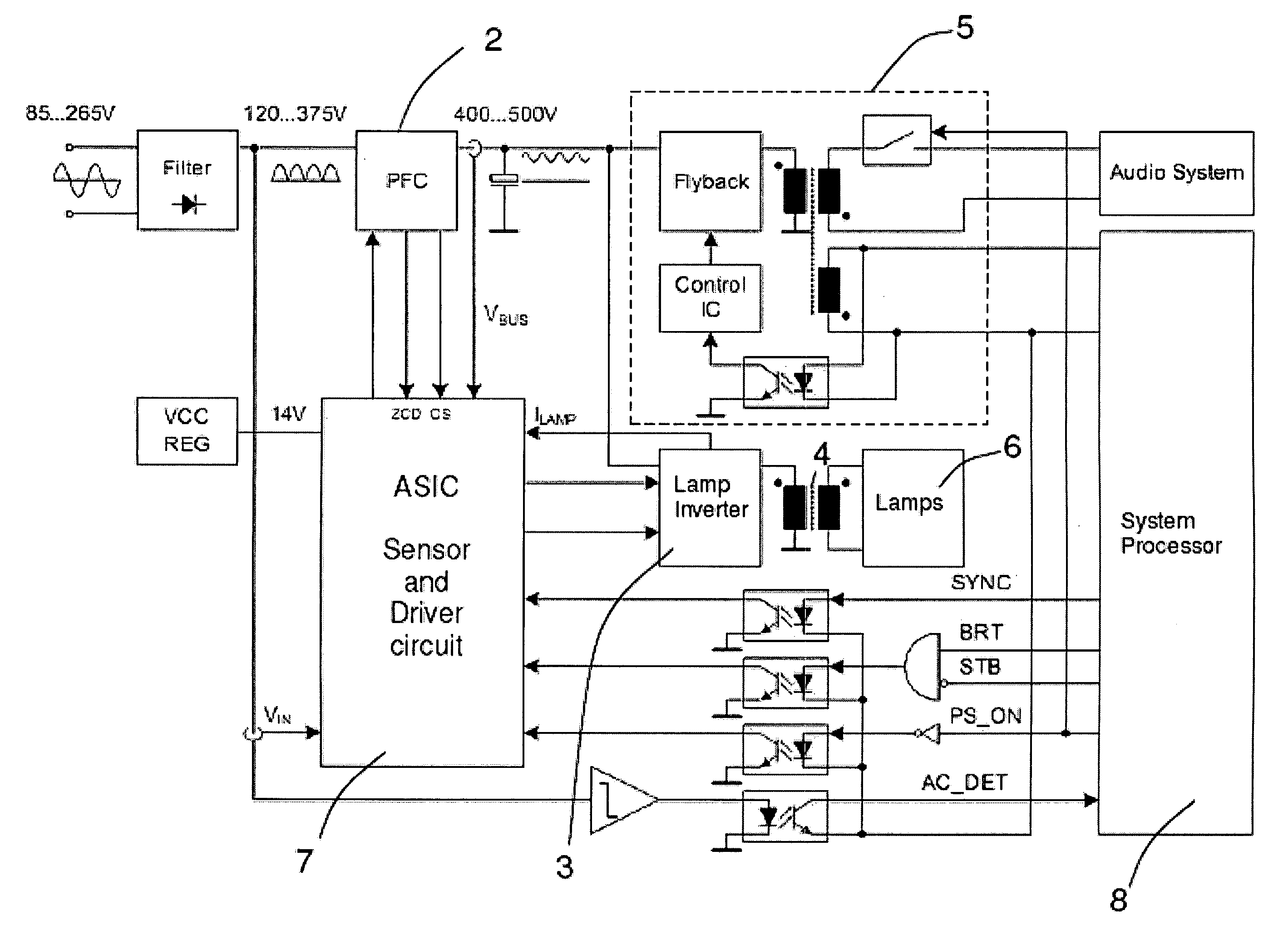
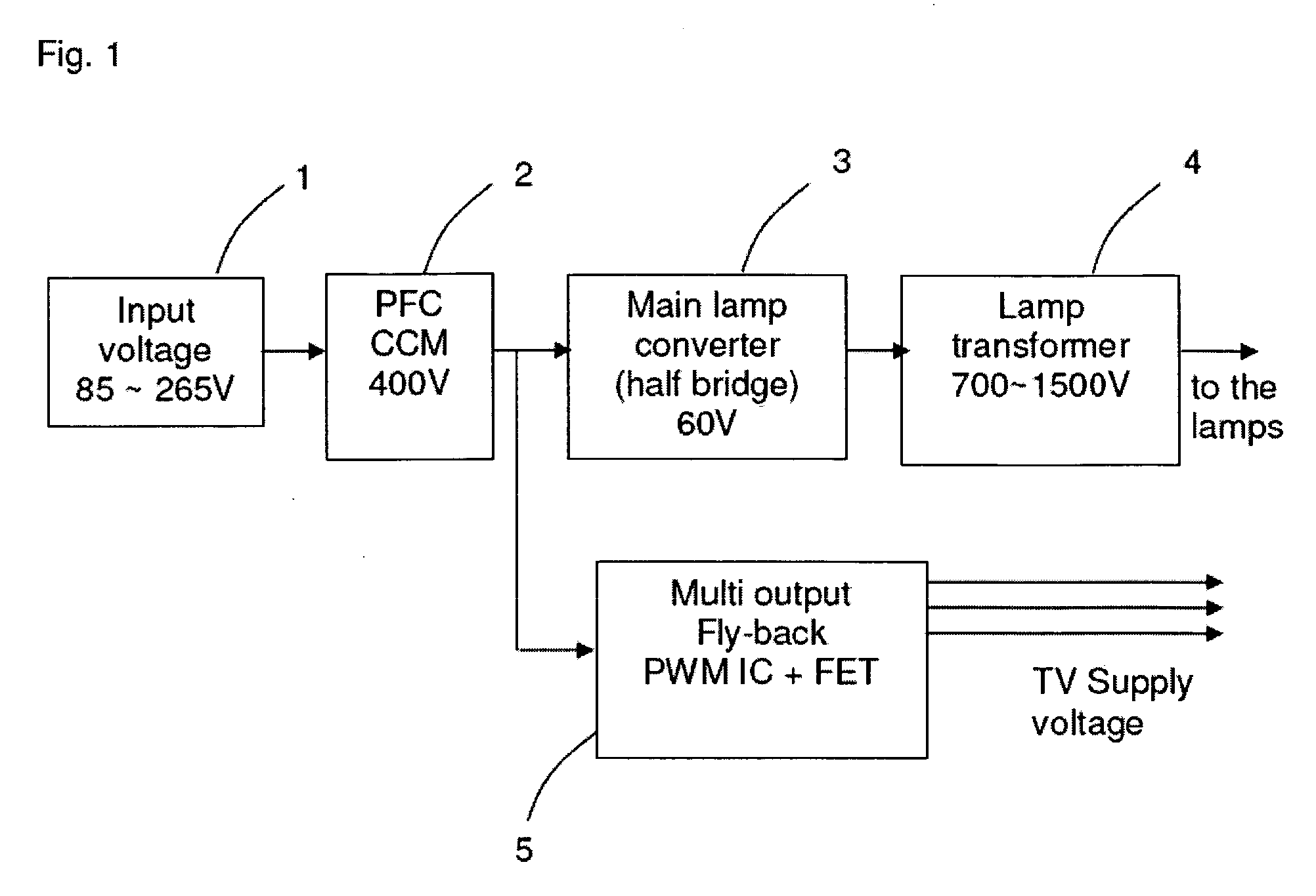
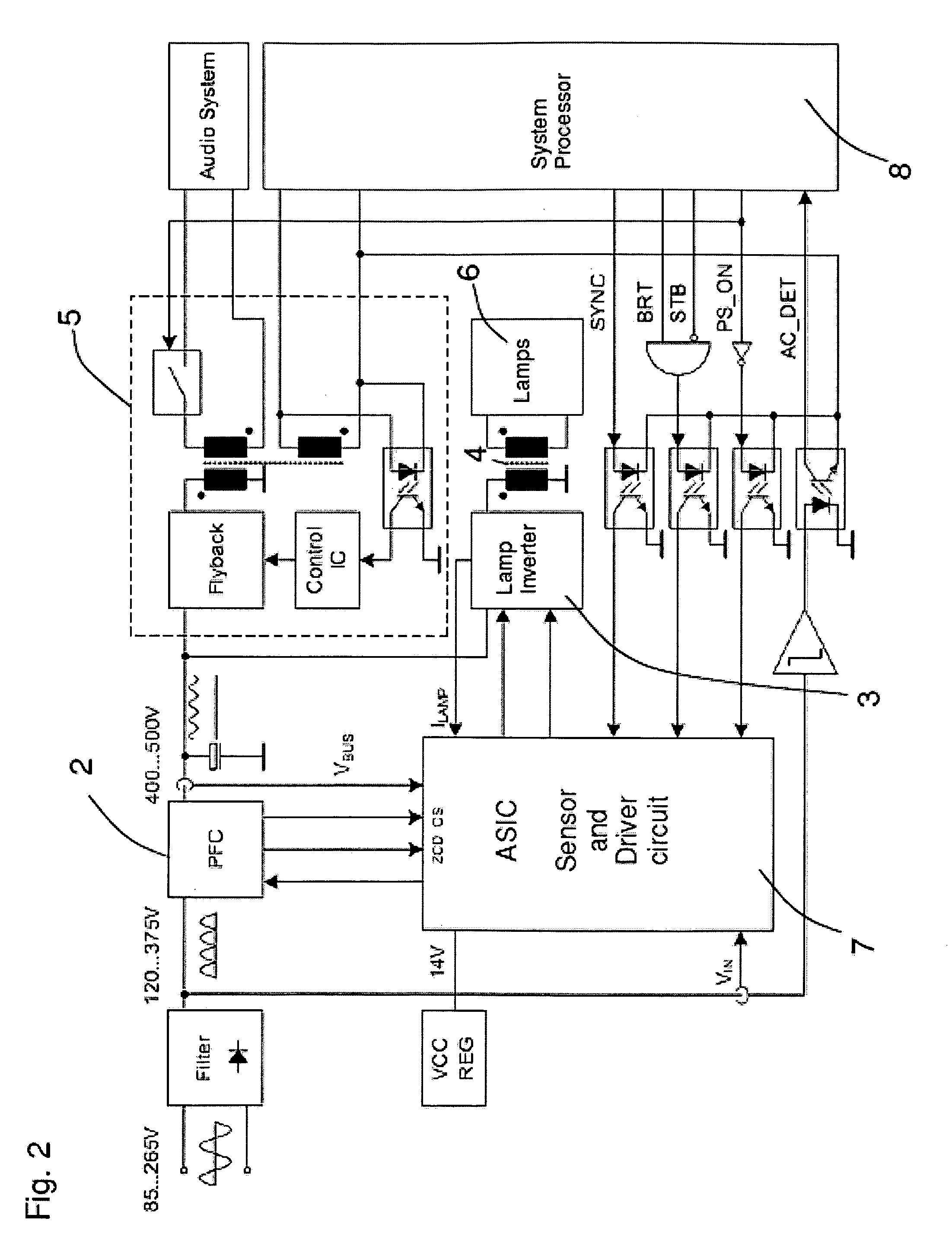
[0020]FIG. 1 shows a block diagram of the circuit for controlling gas discharge lamps according to the invention. The circuit has an input stage 1 that generates an input voltage of 85 to 265 volts DC current. This input voltage is generated from conventional mains voltage by means of rectification. The input voltage is fed to a power factor correction stage 2 in which a power factor correction (PFC) is implemented. The power factor correction preferably takes place on the boundary between discontinuous and continuous conduction mode (CCM: critical conduction mode). The output voltage of the power factor correction stage 2 is about 400 volts, which is then fed to a lamp converter 3. The lamp converter 3 is designed as a direct current / alternating current inverter (DC / AC inverter) having a half-bridge circuit. The half-bridge circuit of the lamp converter 3 drives a lamp transformer 4 that transforms the primary voltage that is supplied by the lamp inverter 3 into a secondary voltage...


PUM


Abstract

The invention relates to a method and a device for controlling gas discharge lamps using a direct current/alternating current inverter (DC/AC inverter) that is operated at a predetermined frequency and that generates an AC output voltage U for operating the gas discharge lamps from a DC input voltage which has a residual ripple. According to the invention, the DC/AC inverter is operated in zero voltage switching (ZVS) mode, wherein the DC input voltage is used as the control variable for the lamp current IL, wherein fluctuations in the lamp current IL caused by the residual ripple of the DC input voltage are compensated by a variation in the switch-on times and/or switch-off times of the switching elements QH, QL of the DC/AC inverter.

Description

[0001]The invention relates to a method for controlling gas discharge lamps, particularly an amalgamation of gas discharge lamps for backlighting an LCD display. These kinds of LCD displays are used, for example, in televisions or as computer screens.PRIOR ART[0002]A known method for realizing the backlighting in LCD displays is to use gas discharge lamps that are operated at a voltage of 500 to 1500 V. In the future, the system power supply and light converters for LCD televisions will be integrated together on LIPS (lighting power supply) boards. A LIPS board substantially consists of an input stage for power factor correction (PFC input stage), a flyback converter that supplies the audio and video circuits of the television and a DC / AC inverter that supplies the gas discharge lamps and ensures reliable electrical isolation via an isolating transformer. The power switches of the DC / AC inverter are hard switching and do not produce any considerable switching losses. As part of the ...

Claims


Application Information

Patent Timeline
Patent Type & Authority Applications(United States)
IPC IPC(8): H05B37/02
CPCH05B41/2828
Inventor SCHLENK, MANFREDWEGER, ROBERTHOFFMANN, HANSRAYKHMAN, MYKHAYLOHERFURTH, MICHAELFELDTKELLER, MARTIN
Owner MINEBEA CO LTD
Why Eureka
Try Eureka