
Systems and methods for computer input

a computer input and system technology, applied in the field of keyboards, can solve the problems of specialized keyboards, users can be uncomfortable, and the space of a typical keyboard key is limited,

Inactive Publication Date: 2006-10-26
IKEYINFINITY
View PDF9 Cites 78 Cited by
  • Summary
  • Abstract
  • Description
  • Claims
  • Application Information

AI Technical Summary

Benefits of technology

[0011] In another aspect, the keyboard can include a central processing unit, such as a microprocessor. The processor can execute instructions necessary to control the display device or devices, and any other keyboard functio

Problems solved by technology

As with the example above, the additional function can be accessed by depressing a key along with one or more other keys, such as the Shift key, Control key, and Alternate key; however, space on a typically keyboard key can be limited and therefore, it may be difficult to display all of the functions that a key can perform.
These specialized keyboards can create some discomfort for users, for example, when a user must deal with multiple languages.
These solutions are, however, limited.
Transparent or opaque plastic covers can be used to customize a keyboard, but can be difficult to change from application to application.
Keyboard “kidgloves” or silicon “skins” can be cumbersome.
Interchangeable key sets can be time consuming to change.
Specially manufactured keyboards or customized keyboards can also be cumbersome since different keyboards for different applications need to be stored between each use.

Method used


Image

  • Systems and methods for computer input
  • Systems and methods for computer input
  • Systems and methods for computer input

Examples


Embodiment Construction

.”

BRIEF DESCRIPTION OF THE DRAWINGS

[0014] Features, aspects, and embodiments of the inventions are described in conjunction with the attached drawings, in which:

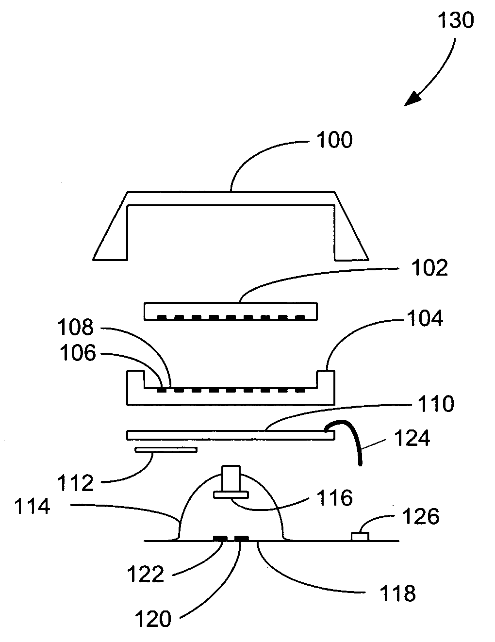
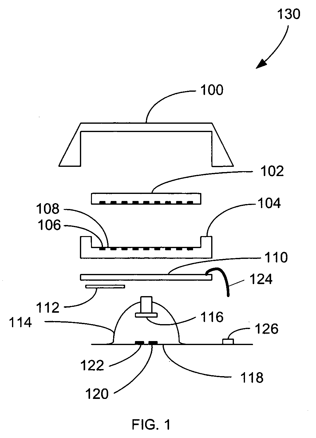
[0015]FIG. 1 is a diagram illustrating components that comprise an example key configured in accordance with one embodiment;

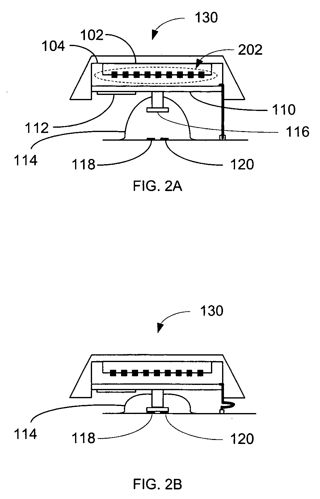
[0016]FIG. 2A is a diagram illustrating the components of FIG. 1 assembled to form a key;

[0017]FIG. 2B is a diagram illustrating the key of FIG. 2A in a depressed position;

[0018]FIG. 3 is a diagram illustrating a top view of the key of FIG. 2A;

[0019]FIG. 4 is a diagram illustrating an example display that can be included in the components of FIG. 1;

[0020]FIG. 5 is a diagram illustrating pixels comprising the display of FIG. 4;

[0021]FIG. 6A-C are diagrams illustrating a portion of a keyboard that includes the key of FIG. 2A;

[0022]FIG. 7 is a diagram illustrating a system that includes the keyboard of figures 6A-6C;

[0023]FIG. 8 is a block diagram illustrating various components of the keyboard o...


PUM


Abstract

A display device, such as a liquid crystal display, can be integrated into each key of a keyboard, numeric keypad, or other keyed input device. The display device can display a symbol when it is active. For example, a “1” when pressing that key will input a “1” and a “!” when that key input a “!.” In addition to a display device, each key top can include a key cap, generally made of a transparent plastic so that the display can be seen. The key cap can be formed in the shape of a key and will generally be the portion of the input device that a user presses on to input information. A plurality of key caps can be combined to form a keyboard, numeric keypad, or other keyed input device. Throughout the rest of this application the term keyboard will generally be used in place of keyboard, numeric keypad, or other keyed device. In another embodiment a display device can be overlaid with a key cap skin to form a keyed input device, such as a keyboard. The display device can be a touch sensitive screen. Each key on the key cap skin can be pressed to input information displayed on the touch sensitive screen below. The key cap skin provides keys that are tactilely discernible without activating the keys. Individual keys can be located and distinguished from adjacent keys by touch.

Description

BACKGROUND [0001] 1. Field of the Inventions [0002] The field of the invention relates generally to computer input devices and more particularly to keyboards. [0003] 2. Background Information [0004] Information can be input into computers and other electronic devices using a keyboard or keypad. Generally, the keyboard or keypad includes a static symbol on each key according to a specific alphabetic or functional layout. In certain layouts, the keys can include multiple static symbols to indicate multiple functions. For example, on many computer keyboards in the United States the “1” and the “!” are displayed on the same key. When the “1” key is pressed a “1” can be input into the computer, however; when the “Shift Key” and the “1” key are pressed together a “!” can be input into the computer. [0005] In certain layouts, the keyboard keys can have more than two functions. As with the example above, the additional function can be accessed by depressing a key along with one or more othe...

Claims


Application Information

Patent Timeline
IPC IPC(8): B41J5/00
CPCG06F3/0238
Inventor GRANT, BRUCE D.R.
Owner IKEYINFINITY
Learn More