Card connector

Inactive Publication Date: 2006-10-26
DDK LTD
View PDF2 Cites 30 Cited by
  • Summary
  • Abstract
  • Description
  • Claims
  • Application Information

AI Technical Summary

Benefits of technology

[0013] It is an object of the invention to provide a card connector which overcomes the disadvantages of the prior art described

Problems solved by technology

Such a limitation of area occupied by the substrate necessarily leads to the use of a plurality of substrates.
On the other hand, if a plurality of connectors are required for exchanging a plurality of memory cards, information appliances would become bulky which would be inconvenient for carrying them.
In the case that there is a limitation in height, particularly, the card connectors as disclosed in the Patent Literatures 1 to 4 cannot achieve miniaturization in height of co

Method used


Image

  • Card connector
  • Card connector
  • Card connector

Examples


Embodiment Construction

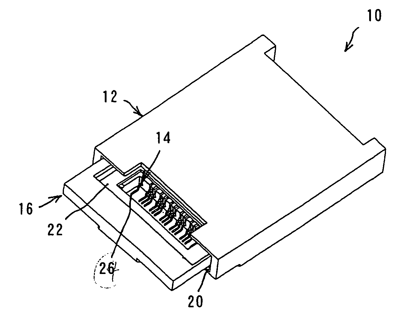
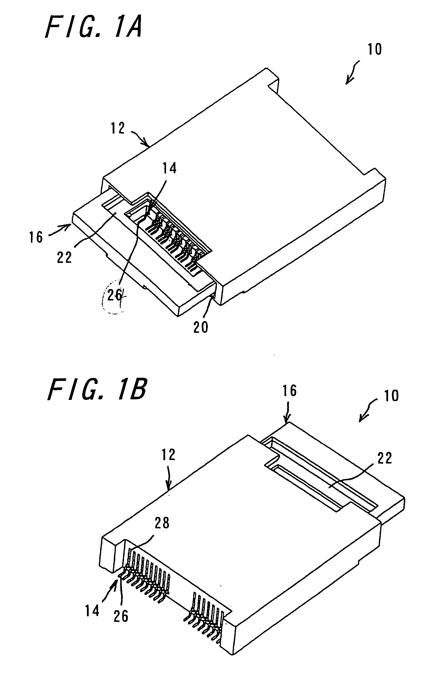
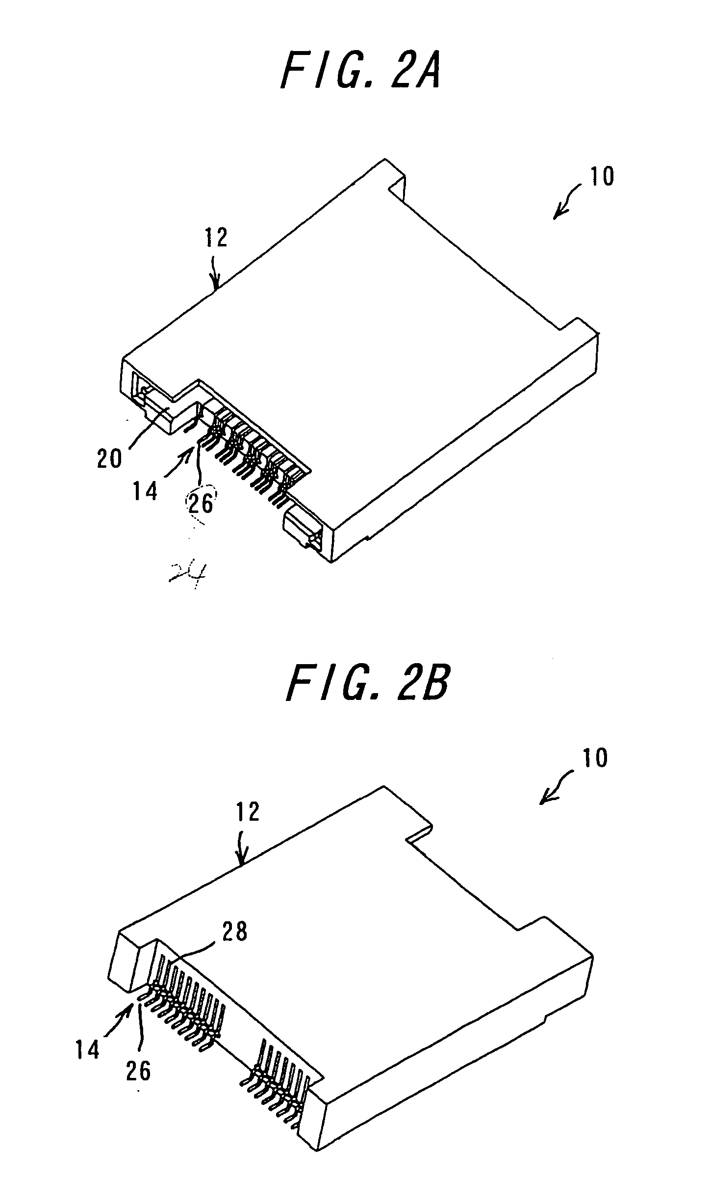
[0038] One embodiment of the invention will be explained with reference to FIGS. 1A to 6I. FIG. 1A is a perspective view of a card connector according to the invention viewed from the fitting opening side, while FIG. 1B is a perspective view of the card connector shown in FIG. 1A viewed from the opposite side of the fitting opening. FIG. 2A is a perspective view of the card connector similar to FIG. 1A with the tray removed, and FIG. 2B is a perspective view of the card connector similar to FIG. 1B with the tray removed. FIG. 3A is a perspective view of the tray used in the card connector according to the invention, while FIG. 3B is a perspective view of the tray with one card 60 mounted therein. FIG. 4A is a perspective view of the tray used in the card connector, and FIG. 4B is a perspective view of the tray with a plurality of cards mounted therein. FIG. 5 is a perspective view of the card connector with the tray drawn, viewed from the fitting opening side. FIGS. 6A to 6I are vie...


PUM


Abstract

A card connector which is able to be connected to at least two cards, includes contacts corresponding to the number of the cards, a tray in which at least two cards can be mounted, and a housing having a fitting opening for receiving the tray therein and for arranging and holding the contacts. Also, a card connector which is able to be connected to four cards, includes four kinds of contacts, a tray having card mounting sections in which four cards can be mounted, and a housing having a fitting opening for receiving the tray therein and for arranging and holding the four kinds of contacts. With these constructions, miniaturization in height or reduced overall height of connector is possible with a simple construction.

Description

BACKGROUND OF THE INVENTION [0001] This invention relates to a card connector for use in electric and electronic appliances in instruments and for use in printers and card readers and more particularly to a card connector miniaturized in height by the use of a tray. [0002] There have been many kinds of cards as media for a wide variety of information. It has been a common practice to acquire or store various information from or onto a card inserted into a card connector connected to an information appliance. [0003] In order to connect cards to a card connector, the connector may be provided with a plurality of fitting openings for receiving a required number of cards therein, and contact portions of contacts may extend into the fitting openings so as to bring the cards into contact with the contact portions of the contacts, thereby achieving continuity therebetween. [0004] With these card connectors, it may be considered that there are provided fitting openings of the number corresp...

Claims


Application Information

Patent Timeline
IPC IPC(8): H01R24/00
CPCG06K7/0021G06K7/0073G06K7/0034
Inventor KIKUCHI, HITOSHITAKAHASHI, HIROKAZUTAKEI, KAZUNORIKATO, HIROMICHI
Owner DDK LTD
Why Eureka
Try Eureka