E-mail messaging to/from a mobile terminal

a mobile terminal and electronic mail technology, applied in the field of electronic mail to/from a mobile terminal, can solve the problems of not supporting, unable to support, and the prior art technique described suffers from certain limitations,

Inactive Publication Date: 2006-10-26
SEVEN NETWORKS INC
View PDF17 Cites 118 Cited by
  • Summary
  • Abstract
  • Description
  • Claims
  • Application Information

AI Technical Summary

Benefits of technology

[0008] An advantage of the invention is more seamless integration of e-mail processing between the host system and the mobile terminal. For example, [0009] provisioning of mobile e-mail is possible without affecting e-mail configuration of the host system; [0010] messages sent or deleted at the mobile terminal are automatically moved to the respective folder at the host system, ie, the “sent items” or “deleted items” folder.
[0009] provisioning of mobile e-mail is possible without affecting e-mail configuration of the host system;
[0010] messages sent or deleted at the mobile terminal are automatically moved to the respective folder at the host system, ie, the “sent items” or “deleted items” folder.

Problems solved by technology

The above-described prior art technique suffers from certain limitations.
Some e-mail systems support a .forward-type file for forwarding e-mail messages from a first e-mail account to a second e-mail account, but some systems do not support it.
It is difficult to set up e-mail systems that do not support such forwarding techniques.
Furthermore, the Gilhuly patent does not address issues that relate to manipulating e-mail messages at the second e-mail account (at the mobile terminal).
For instance, it is difficult or impossible to use the terminal to arrange incoming e-mail messages into different folders at the host system.
A further related problem is that e-mail messages that the user has read at the terminal may appear as unread messages at the host system.
Yet another problem is that configuring an e-mail client software at the mobile terminal is difficult because of user interface restrictions in typical mobile terminals.

Method used


Image

  • E-mail messaging to/from a mobile terminal
  • E-mail messaging to/from a mobile terminal
  • E-mail messaging to/from a mobile terminal

Examples


Embodiment Construction

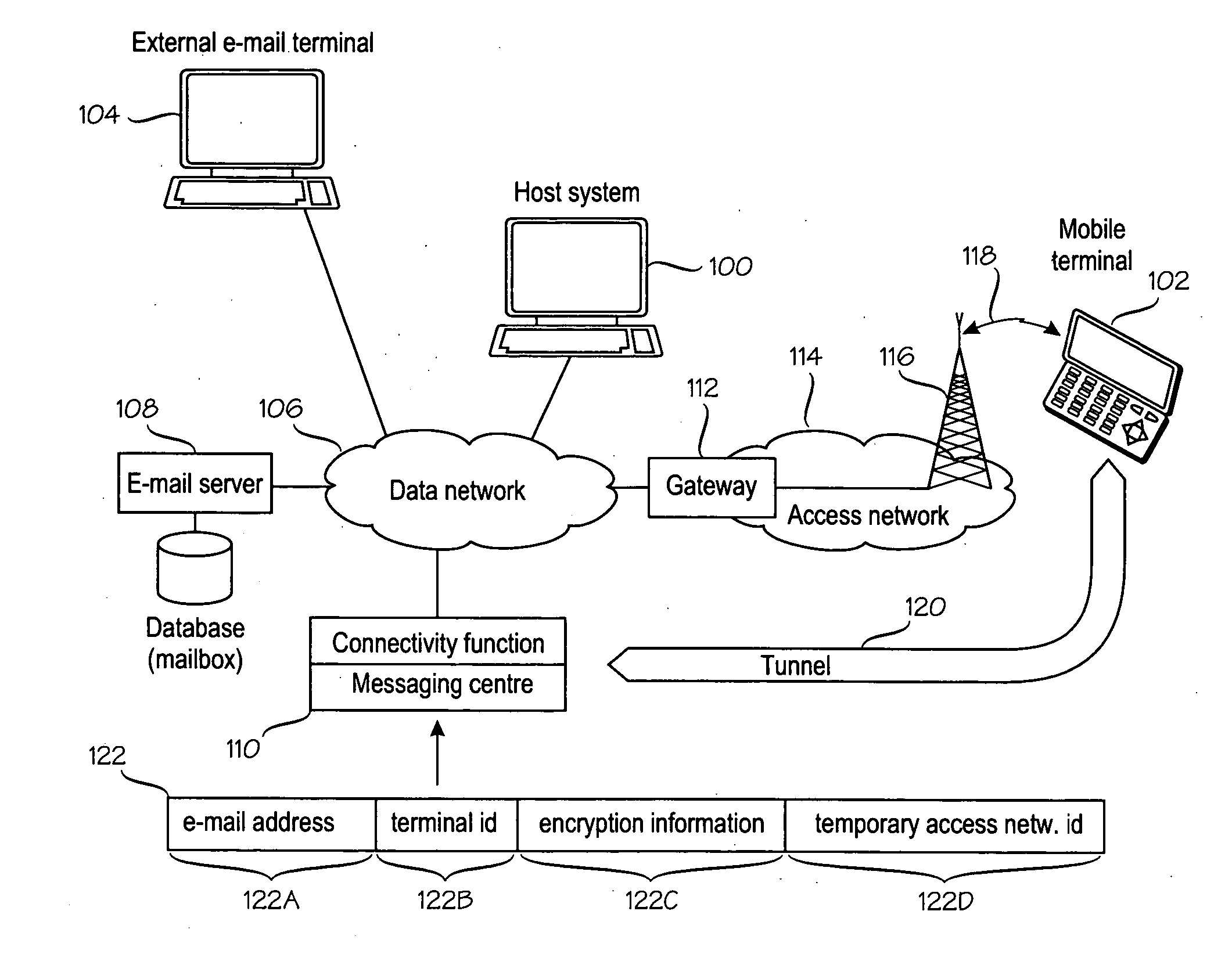
[0019]FIG. 1 shows an exemplary system architecture in which the invention can be used. Reference numeral 100 denotes a host system that is able to send an receive e-mail messages. Reference numeral 102 denotes a mobile terminal, also able to send an receive e-mail messages. The e-mail messages may originate or terminate at external e-mail terminals, one of which is denoted by reference numeral 104. The invention aims at improving cooperation between the host system 100 and mobile terminal 102 such that they can use a single e-mail account as transparently as possible. This means, for example, that the users of the external e-mail terminals 104, when sending or receiving e-mail, do not need to know if the user of the host system 100 actually uses the host system 100 or the mobile terminal 102 to communicate via e-mail. The transparency also means that e-mail manipulation at the mobile terminal 102 has, as far as possible, the same effect as the corresponding e-mail manipulation at t...


PUM


Abstract

Systems and methods for sharing an e-mail address between a host system (100) and a mobile terminal (102) addressable by a temporary wireless identity (122D) in an access network (114). A terminal identifier (122A) is assigned to the mobile terminal (102) or its user. The system comprises a connectivity function (600) and a messaging centre (110) that collectively maintain an association (610, 612) between the terminal identifier (122A), encryption information (122C) and the temporary wireless identity (122D). When detecting an e-mail message addressed to the terminal identifier (122A), the connectivity function encrypts the e-mail message with the encryption information (122C). The messaging centre determines the temporary wireless identity (122D) of the mobile terminal and transmits the encrypted e-mail message to the mobile terminal which receives and decrypts the encrypted e-mail message.

Description

BACKGROUND OF THE INVENTION [0001] The invention relates to methods and equipment for transmitting electronic mail (e-mail) messages to or from a mobile terminal. [0002] U.S. Pat. No. 6,701,378 to Barry Gilhuly et al. discloses a system and method for pushing information, such as e-mail messages, from a host system to a mobile data communication device (mobile terminal). The technique permits e-mail processing at a mobile terminal in addition to a more stationary computer, referred to as a host system in the Gilhuly patent. Specifically, a redirector program operating at the host system enables a user to continuously redirect certain user-selected data items from the host system to the user's mobile data communication device upon detecting that one or more user-defined triggering events has occurred. The redirector program operates in connection with event-generating applications and repackaging systems at the host system to configure and detect a particular user-defined event, and ...

Claims


Application Information

Patent Timeline
Patent Type & Authority Applications(United States)
IPC IPC(8): H04L12/58H04Q7/38H04Q7/22H04W4/12H04W8/26
CPCH04L12/5895H04L51/38H04L63/0428H04L63/08H04W12/06H04W4/12H04W8/26H04W12/02H04L63/18H04W12/033H04L51/58
Inventor BACKHOLM, ARISALORINNE, SEPPOSAARILAHTI, ANTTIKETONEN, MARKOVUORNOS, LAURISALMI, PETRI
Owner SEVEN NETWORKS INC
Why Eureka
Try Eureka