Thermal signature intensity alarmer system and method for processing thermal signature
a technology of alarmer system and thermal signature, which is applied in the direction of optical radiation measurement, instruments, and sensing radiation from moving bodies, etc., can solve problems such as thermal signature changes, false alarms, and noisy visual environmen
- Summary
- Abstract
- Description
- Claims
- Application Information
AI Technical Summary
Benefits of technology
Problems solved by technology
Method used
Image
Examples
example 1
[0054] A human who is a mile from a system, as per in the present invention, registers as a single pixel in an image. Although the single pixel is within the object thermal threshold (e.g., z % thermal intensity difference), the overall effect on the average thermal signature of the image is too small to warrant an alarm.
[0055] In this way, large warm objects that are beyond a desired range of interest (e.g., not within 50 yards of the sensor) can be ignored and not produce false alarms.
example 2
[0056] A small rodent (e.g., rat) inside the range of interest is detected. Its thermal image is placed within the object thermal threshold (e.g., z % thermal intensity difference). Although more than one pixel may be affected, its overall effect on the average thermal signature of the image would be too small to warrant an alarm.
[0057] In this way, small warm objects that are within the desired range of interest can also be ignored and not produce false alarms.
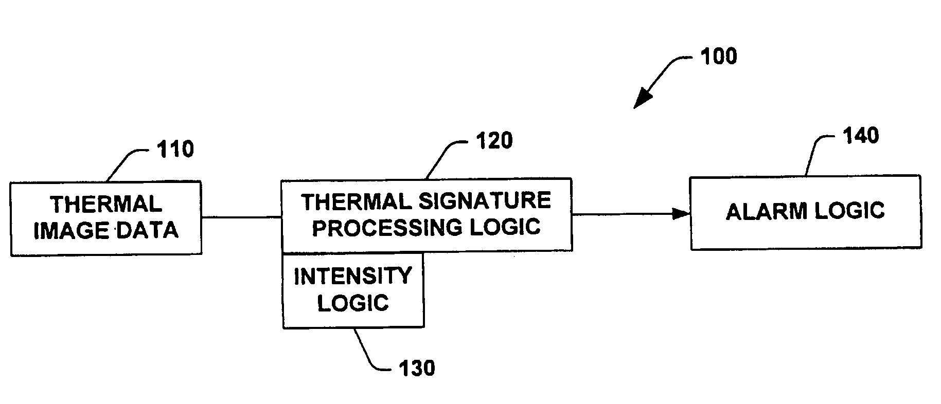
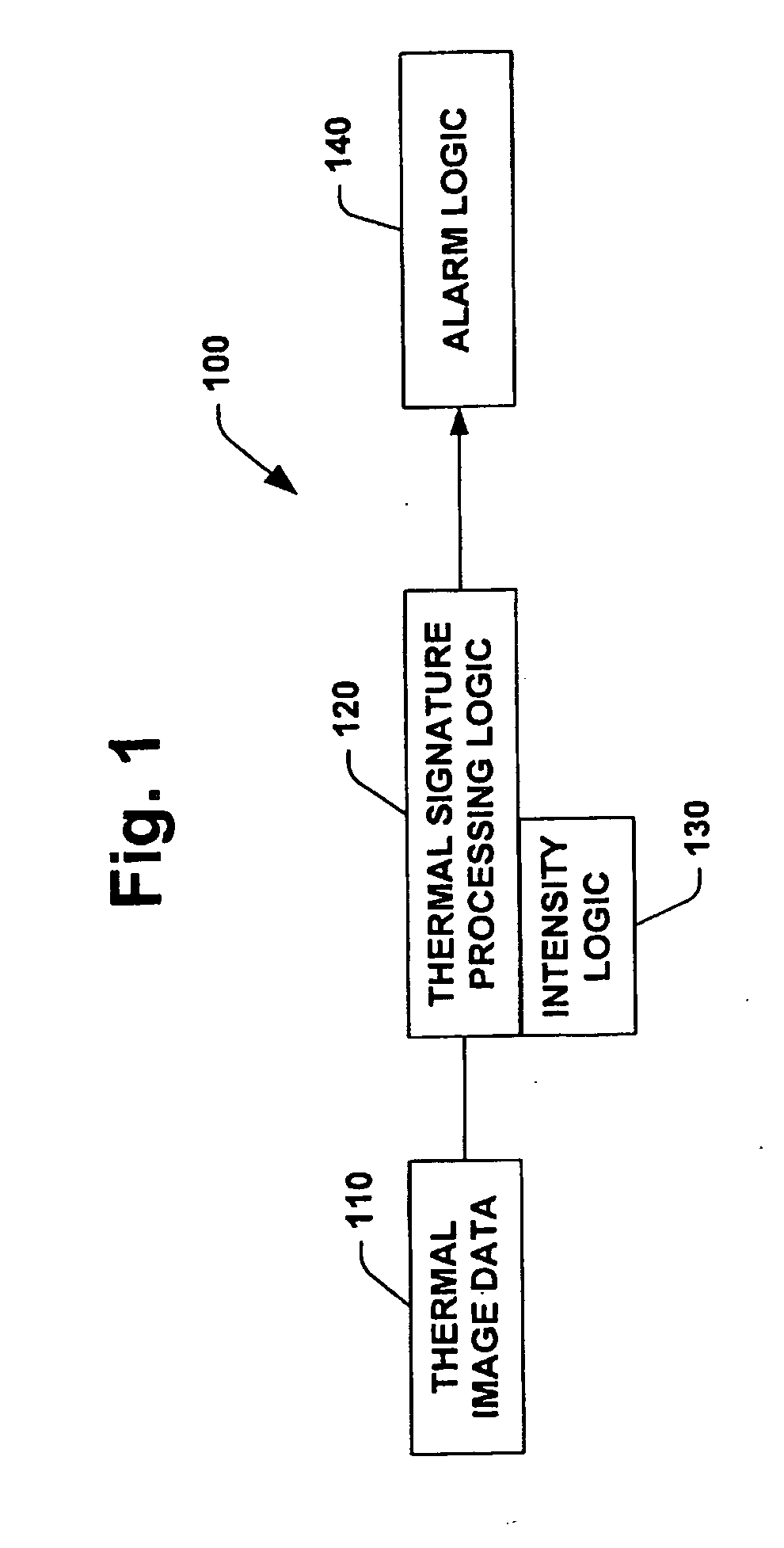
[0058] Thus, the alarm logic 140 can determine whether an alarm-worthy event has occurred based on threshold values produced by the thermal signature processing logic 120. Alternatively, the alarm logic 140 can also determine whether an alarm-worthy event has occurred based on the values that are produced by processing the effect an individual pixel or set of pixels has on an average value for a region of interest utilizing the intensity logic 130. In a preferred embodiment, alarm logic 140 can utilize both the signature pr...
example 3
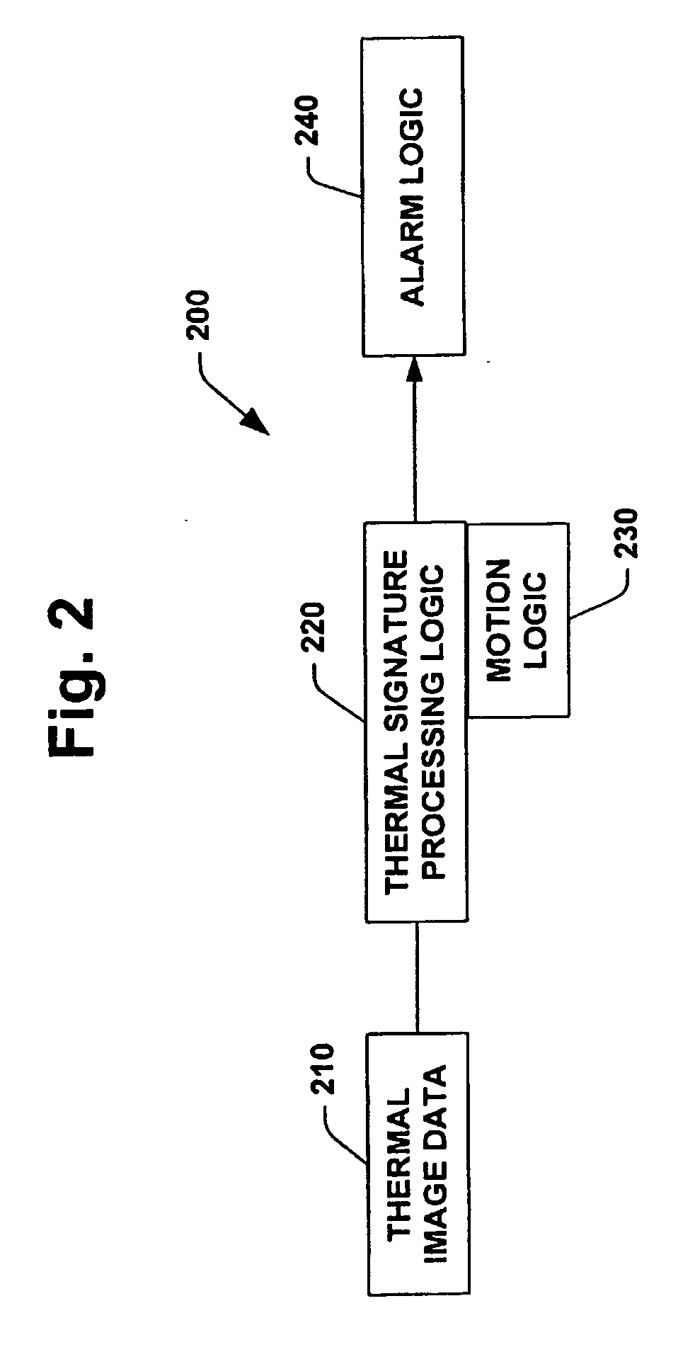
[0073] A warm object (e.g., small rodent) moves across a region of interest in a field of view. Thermal signature processing identifies that an object within specified thermal intensity parameters is in the field of view. For example, an object's thermal threshold may be examined to determine whether the object is warm enough to be of interest without being too warm (e.g., x % warmer than the background in the field of view without being y % warmer). Then, visual frame difference analysis determines that the item with the interesting thermal signature has moved by identifying such movement as the object's path, its location and other such parameters. By utilizing the thermal intensity parameters and the visual frame analysis, the systems of the present invention can determine whether an alarm-generating event has occurred. Thus, combination processing can determine whether the occurrence is an alarm-worthy event.
[0074] The systems of the present invention can also determine, via vi...
PUM
 Abstract
Description
Claims
Application Information
 - R&D
- Intellectual Property
- Life Sciences
- Materials
- Tech Scout
- Unparalleled Data Quality
- Higher Quality Content
- 60% Fewer Hallucinations
Browse by: Latest US Patents, China's latest patents, Technical Efficacy Thesaurus, Application Domain, Technology Topic, Popular Technical Reports.
© 2025 PatSnap. All rights reserved.Legal|Privacy policy|Modern Slavery Act Transparency Statement|Sitemap|About US| Contact US: help@patsnap.com


