
Spherical motion mechanism

a motion mechanism and spherical technology, applied in the field of mechanical linkages, can solve the problems of reducing the stiffness of the link, reducing the efficiency affecting the operation of the operating room, so as to achieve the effect of reducing reducing the weight of the typical system, and increasing the size of the typical system

Inactive Publication Date: 2006-11-02
UNIV OF WASHINGTON
View PDF23 Cites 46 Cited by
  • Summary
  • Abstract
  • Description
  • Claims
  • Application Information

AI Technical Summary

Problems solved by technology

Typical systems are often too large, heavy and cumbersome to be effective in an operating room.
In addition, typical systems are subject to device collisions.
The limitation of a summed isotropy score is that singularities or workspace boundaries could exist within a region that has a good score.
The drawback to larger link angles is a decrease in link stiffness and greater bulk.
The difference in the results is not unexpected but it does pose an interesting dilemma.
However, this design has lower overall performance than the design optimized for the DWS and larger links, which may increase the likelihood for problems of collisions between two manipulators.
However as discussed earlier, optimization on a 90° cone may result in a design that is larger than needed.
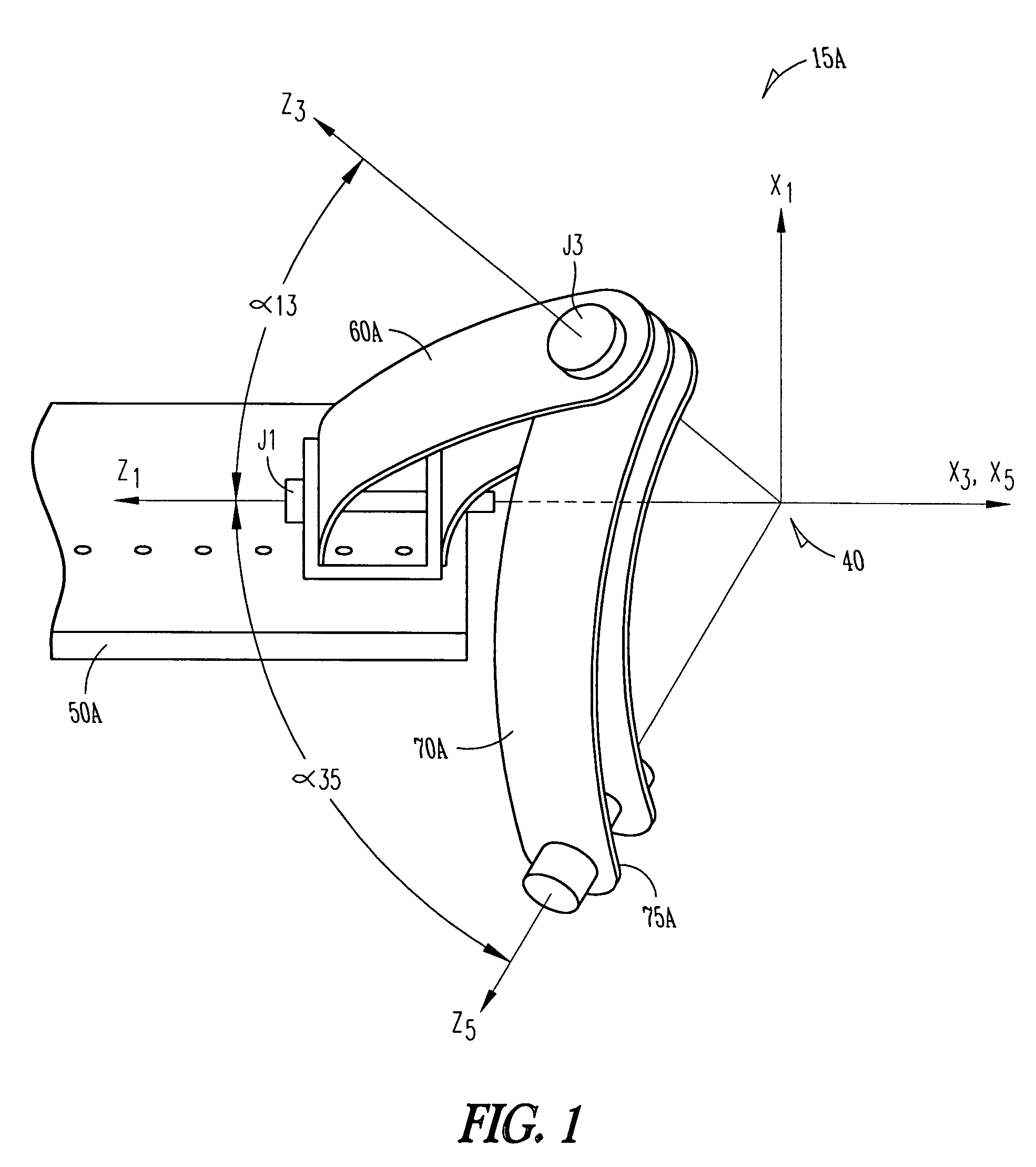
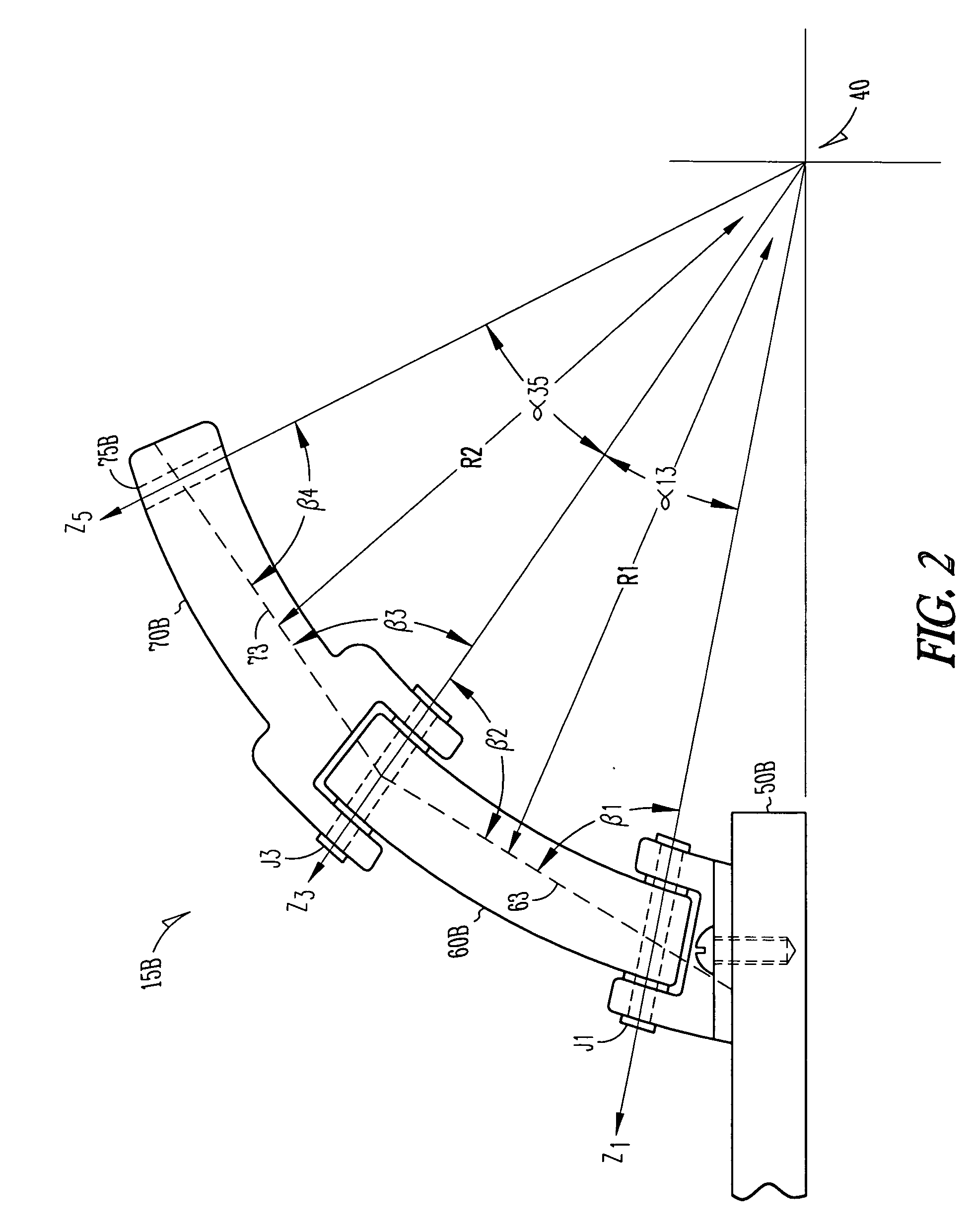
As such, the motion of the tool is limited to travel along or about an axis through the center of the sphere.

Method used


Image

  • Spherical motion mechanism
  • Spherical motion mechanism
  • Spherical motion mechanism

Examples


Embodiment Construction

[0010] The following detailed description includes references to the accompanying drawings, which form a part of the detailed description. The drawings show, by way of illustration, specific embodiments in which the invention may be practiced. These embodiments, which are also referred to herein as “examples,” are described in enough detail to enable those skilled in the art to practice the invention. The embodiments may be combined, other embodiments may be utilized, or structural, logical and electrical changes may be made without departing from the scope of the present invention. The following detailed description is, therefore, not to be taken in a limiting sense, and the scope of the present invention is defined by the appended claims and their equivalents.

[0011] In this document, the terms “a” or “an” are used, as is common in patent documents, to include one or more than one. In this document, the term “or” is used to refer to a nonexclusive or, unless otherwise indicated. F...


PUM


Abstract

This document discusses, among other things, a mechanism for providing motion having two degrees of freedom and centered on a single point within a sphere. Methods to design the mechanism consistent with specified parameters are also described.

Description

GOVERNMENT FUNDING [0001] The subject matter described herein was made with U.S. Government support under contract or grant number DAMD17-02-1-0202 entitled “MiniRobot Design for Military Telesurgery in the Battlefield: Breaking the Size Barrier for Surgical Manipulators,” project period May 01, 2002-Apr. 20, 2006, awarded by the Department of the Army. The United States Government has certain rights in the invention.TECHNICAL FIELD [0002] This document pertains generally to mechanical linkages, and more particularly, but not by way of limitation, to a spherical motion mechanism. BACKGROUND [0003] Robotically controlled surgical methods, such as laparoscopy, hold the promise of bringing advanced medical procedures to the battlefield and other remote locations throughout the globe. Typical systems are often too large, heavy and cumbersome to be effective in an operating room. In addition, typical systems are subject to device collisions.BRIEF DESCRIPTION OF THE DRAWINGS [0004] In the...

Claims


Application Information

Patent Timeline
IPC IPC(8): B25J17/00
CPCA61B19/22A61B19/2203Y10T74/20305B25J17/0266B25J18/007A61B2019/2242A61B34/70A61B34/71A61B34/30
Inventor HANNAFORD, BLAKEROSEN, JACOBTRIMBLE, DENNISLUM, MITCHELLMOREYRA, MANUELSINANAN, MIKA
Owner UNIV OF WASHINGTON
Learn More