Telescoping steering shaft

a telescopic, steering shaft technology, applied in the direction of steering columns, steering parts, vehicle components, etc., can solve the problems of difficult to achieve and maintain acceptable telescopic loads, high manufacturing complexity, and high production cost, so as to prevent the disassembly of the lower steering shaft and reduce production costs. , the effect of high precision design

Inactive Publication Date: 2006-11-02
DELPHI TECH INC
View PDF1 Cites 11 Cited by
  • Summary
  • Abstract
  • Description
  • Claims
  • Application Information

AI Technical Summary

Benefits of technology

[0006] According to yet another aspect of the invention, a method for forming a telescopically adjustable vehicular steering column assembly is provided. The method comprises the steps of forming an axially extending receiving chamber in a lower tubular section of an upper steering shaft, forming a lower steering shaft, attaching a guide head to one end of the lower steering shaft, forming an axially extending keyway in the receiving chamber, affixing a key to the guide head, positioning the guide head within the receiving chamber of the lower tubular section with the key in sliding registry with the keyway, and creating a lower stop between the guide head and the receiving chamber to prevent disassembly of the lower steering shaft from the upper steering shaft.
[0007] A steering column assembly made according to the invention is particularly well-suited to creating a high precision design in which a telescoping steering shaft assembly is less costly to produce but at the same time is strong and exhibits good telescoping loads.

Problems solved by technology

Although these current designs are reliable and effective, they are expensive to produce and require a high degree of manufacturing complexity.
Additionally, acceptable telescoping loads are difficult to achieve and maintain.

Method used


Image

  • Telescoping steering shaft
  • Telescoping steering shaft
  • Telescoping steering shaft

Examples


Embodiment Construction

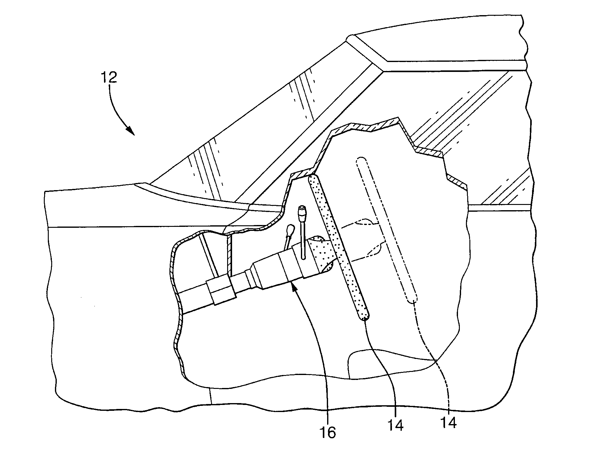
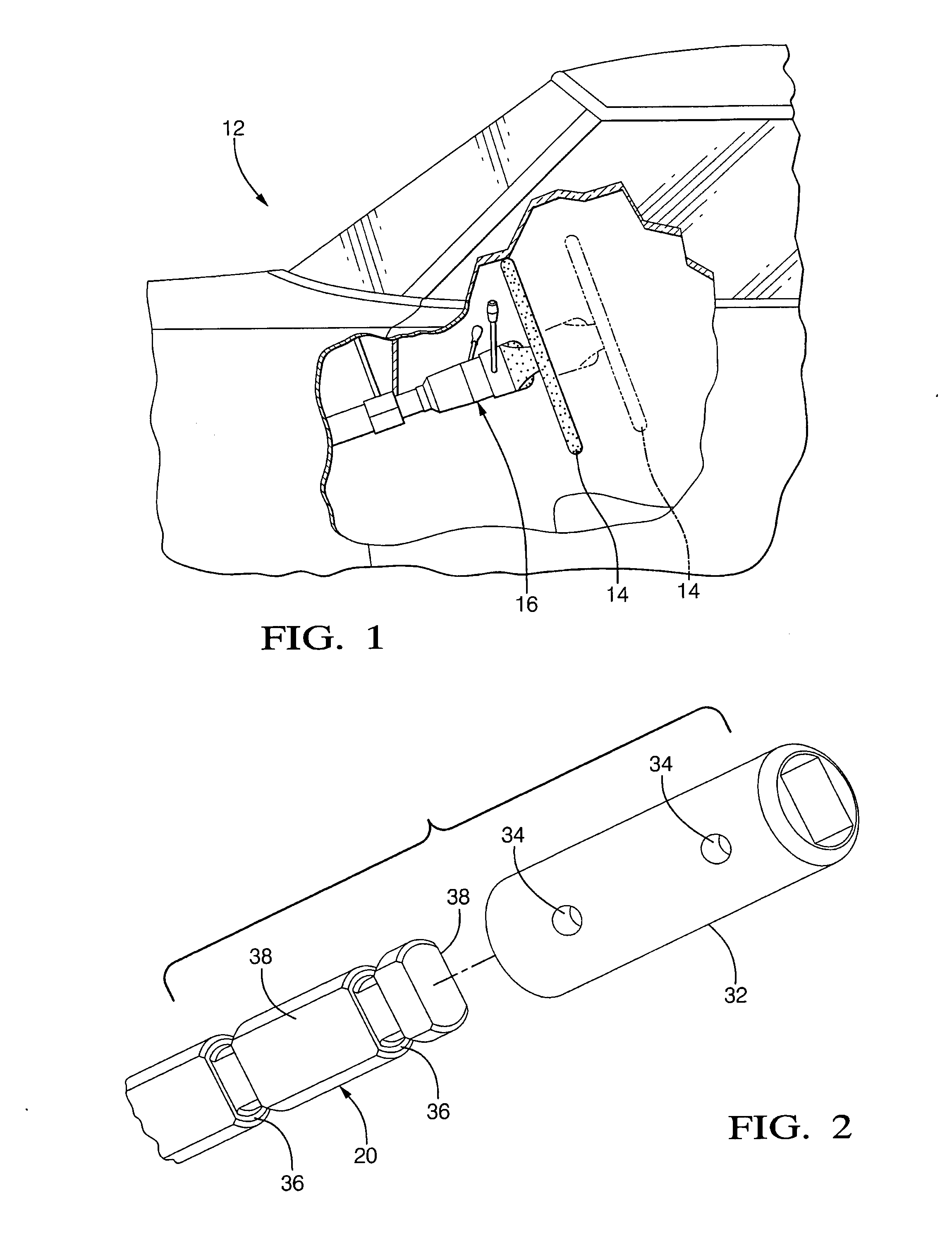
[0019] Referring to the Figures, wherein like numerals indicate like or corresponding parts throughout the several views, a portion of a conventional passenger automobile is generally shown at 12 in FIG. 1. Although the preferred application of the invention is within the field of automobiles 12 and other road vehicles, the invention can be practiced with equal affect in other vehicular fields, including marine and aeronautic applications, as well as non-vehicular fields. Referring again to FIG. 1, however, the automobile 12 is shown including a conventional steering wheel 14 supported at the end of a column assembly, generally indicated at 16. In order to accommodate personal preferences in the positioning of the steering wheel 14, the column assembly 16 is telescopically adjustable so that the steering wheel 14 can be moved to various axially adjusted positions. Although not a subject of this invention, the column assembly 16 can be further modified to provide angular adjustment o...


PUM


Abstract

A telescopically adjustable vehicular steering column assembly (16) includes an upper steering shaft (18, 118) operatively coupled to a lower steering shaft (20, 120). The lower steering shaft (20, 120) is fitted with a guide head (32, 132) which is precision machined to slide within a receiving chamber (28, 128) in the upper steering shaft (18, 188). An axially extending keyway (40, 140) is formed in either the guide head (32) or in the receiving chamber (128) for sliding registry with a key (44, 144). The guide head (32, 132) is affixed to the end of the lower steering shaft (20, 120) through a sheer member (35) which is created by injecting a fluidic plastic material (35) through injection ports (34) so that the plastic forms in injection grooves (36). Once solidified, the plastic material (35) securely affixes the guide head (32, 132) in an operative position on the end of the lower steering shaft (20, 120). However, in the event of a catastrophic collision, the plastic material (35) will sheer, allowing the lower steering shaft (20, 120) to translate into an upper tubular section (22, 122) of the upper steering shaft (18, 118).

Description

FIELD OF THE INVENTION [0001] The invention relates to a telescopically adjustable shaft for a vehicular steering column assembly. BACKGROUND OF THE INVENTION [0002] Many vehicles, and automobiles in particular, are provided with a steering column assembly in which the upper portion, which carries the steering wheel, is arranged for longitudinal adjustment to enable selective telescopic positioning of the steering wheel through a limited range. This arrangement has been found to be exceptionally advantageous in accommodating vehicle operators of varying stature. However, there is a desire to provide such a telescoping steering shaft assembly that is less costly but at the same time strong and exhibits good telescoping loads. [0003] Current production designs of telescoping steering shafts employing multi-tooth splines. A tubular female sleeve surrounds the splined shaft with a plastic over-molded feature there between. Although these current designs are reliable and effective, they ...

Claims


Application Information

Patent Timeline
Patent Type & Authority Applications(United States)
IPC IPC(8): B62D1/16B62D1/18
CPCB62D1/185
Inventor CYMBAL, WILLIAM D.RIEFE, RICHARD K.
Owner DELPHI TECH INC
Why Eureka
Try Eureka