Fire extinguishing system

a technology of fire extinguishing system and compressed gas, which is applied in the direction of applications, functional valve types, transportation and packaging, etc., can solve the problem of limited amount of solution discharged, and achieve the effect of reducing, if not eliminating, the amount of compressible gas in the system

Active Publication Date: 2006-11-02
VIKING
View PDF6 Cites 39 Cited by
  • Summary
  • Abstract
  • Description
  • Claims
  • Application Information

AI Technical Summary

Benefits of technology

[0003] The present invention provides an early suppression fast response (ESFR) preaction system, which uses a fire suppression solution, such as water, foam or, in a cold environment application, an antifreeze solution, such as a propylene glycol antifreeze or potassium lactate, as a supervising medium in the sprinkler piping system of the area being protected. Further, the sprinkler piping system includes one or more air vents to vent the system when the sprinkler system piping is being filled with the fire suppression solution to minimize, if not eliminate compressible gas in the system. The protection system may include a control system with a detection system to provide a single interlock system to control the opening of a control or deluge valve, which may be used to control the delivery of supply water to the sprinkler piping system, and only opens the valve when the detection system detects a fire condition. If a fire is detected by the detection system, the deluge valve will open prior to sprinklers opening and will pressurize system for extinguishing of fire.

Problems solved by technology

Further, in the event of a fire, the control system will stop the flow of antifreeze solution pre-charging the sprinkler system to limit the amount of the antifreeze solution discharged from the sprinkler system in the event of a fire and in the event of a break in the sprinkler piping system so that essentially only a limited amount of the solution will be discharged.

Method used


Image

  • Fire extinguishing system
  • Fire extinguishing system
  • Fire extinguishing system

Examples


Embodiment Construction

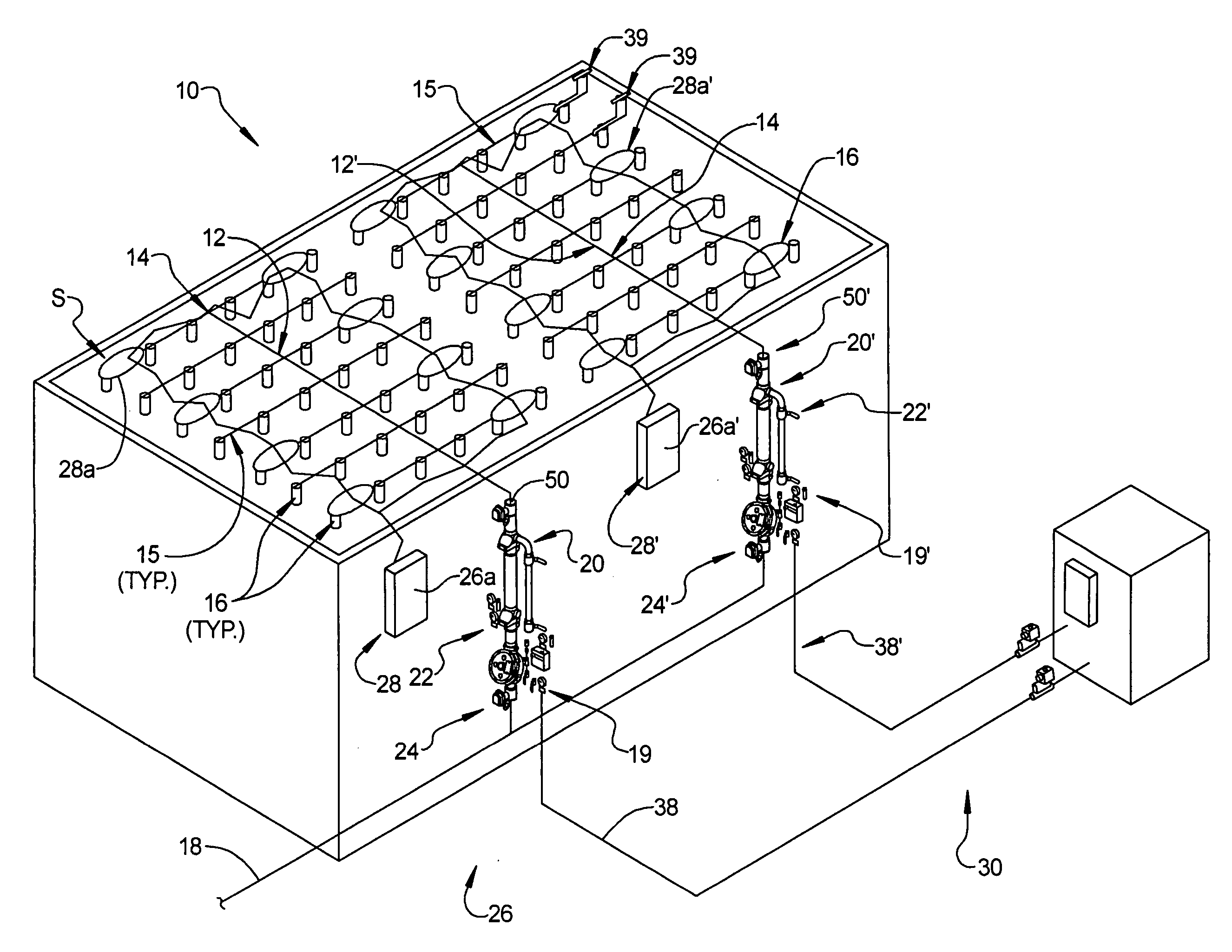
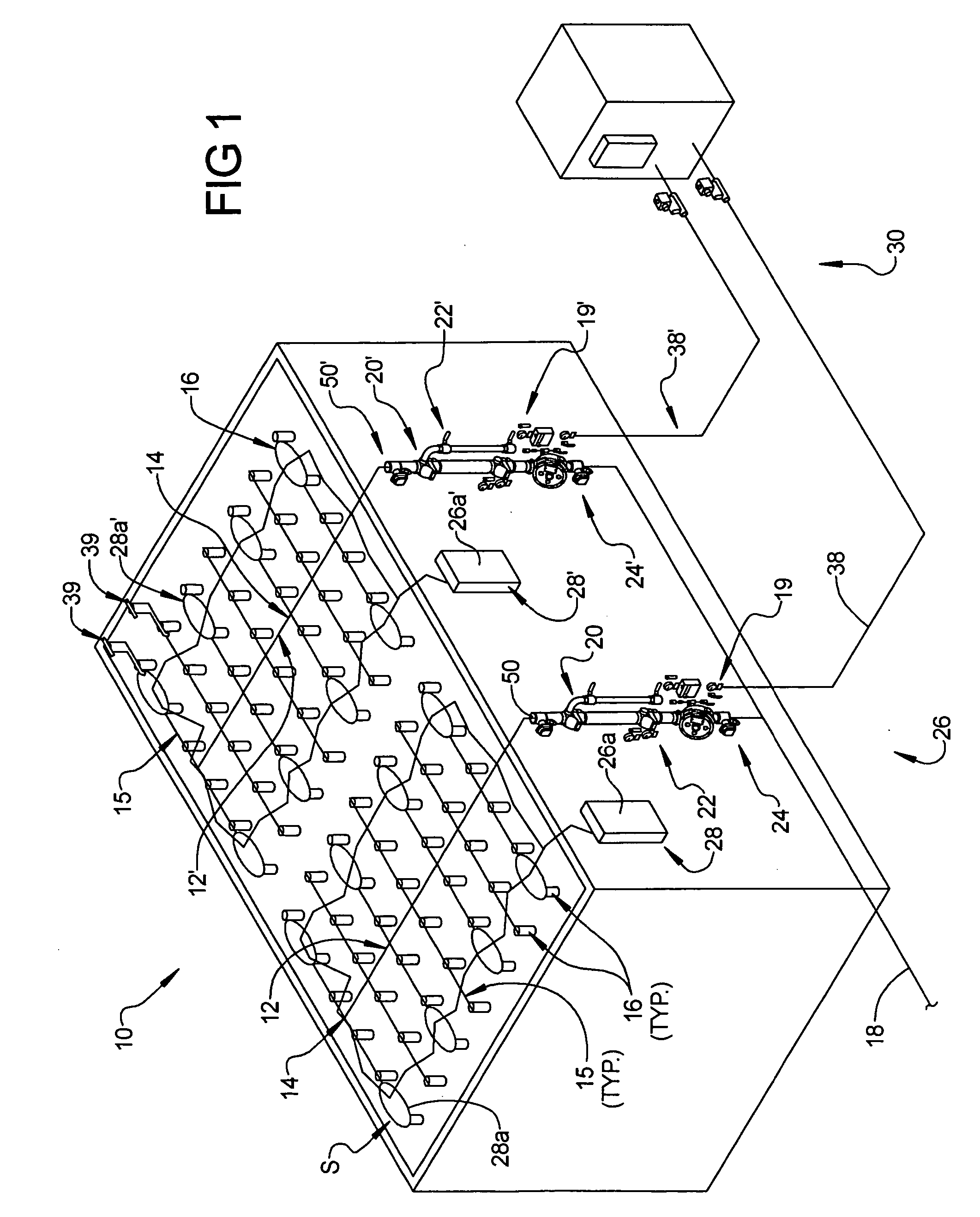
[0038] Referring to FIG. 1, the numeral 10 generally designates an early suppression fast response (ESFR) fire protection system of the present invention that is particularly suitable for unheated environments subject to cold or freezing conditions, including freezer or cold storage applications. Though the invention is not so limited and instead has broad application to where a pre-charged preaction early suppression fast response (ESFR) fire protection system is suitable. In addition, system 10 is preferably pre-primed or pre-charged with a fire suppression solution and may be configured as a single interlock system or a double interlock system depending on its application. As will be more fully described below, system 10 may include two or more sprinkler piping systems 12, 12′ that are selectively filled with plain water from a water supply 18 in the event of a fire condition but pre-charged during a non-fire condition with a fire suppression solution, such as an antifreeze and w...


PUM


Abstract

An early suppression fast response fire protection system includes a sprinkler piping system with at least one sprinkler head assembly, a water supply system, and a check valve in fluid communication with the sprinkler piping system and the water supply system. An antifreeze solution supply system is in fluid communication with the sprinkler piping system, with the check valve isolating the antifreeze solution from the water supply unless a fire condition occurs. A control is provided that is in communication with a flow detector, which detects the pressure of the antifreeze solution in the sprinkler piping system, and a pressure detector, which detects the flow of water through the check valve, and controls the flow of the antifreeze solution to the sprinkler piping system and maintains the pressure of the antifreeze solution in the sprinkler piping system unless the flow detector detects the flow of water through the check valve in which case the control stops the flow of antifreeze solution to the sprinkler piping system to limit the discharge of antifreeze solution from the fire protection system.

Description

[0001] This application is a continuation-in-part application from U.S. application entitled PREACTION FIRE EXTINGUISHING SYSTEM FOR ESFR COLD STORAGE APPLICATIONS, Ser. No. 10 / 935,255, filed Sep. 7, 2004, which claims priority from U.S. provisional application Ser. No. 60 / 500,434, filed Sep. 5, 2003, entitled PREACTION FIRE EXTINGUISHGING SYSTEM FOR ESFR COLD STORAGE APPLICATIONS, which are both incorporated herein in their entireties.TECHNICAL FIELD AND BACKGROUND OF THE INVENTION [0002] The present invention generally relates to fire protection systems and, more particularly, to fire protection systems that have a particularly useful application in unheated environments subject to cold or freezing temperatures, such as cold or refrigerated storage environments; though it should be understood that the concepts of this invention have much broader application and are, therefore, not limited to unheated environments. SUMMARY [0003] The present invention provides an early suppression ...

Claims


Application Information

Patent Timeline
Patent Type & Authority Applications(United States)
IPC IPC(8): A62C35/00A62C35/58A62C35/60
CPCA62C3/004A62C35/60A62C35/58A62C35/00Y10T137/1963
Inventor JACKSON, ELDON D.
Owner VIKING
Why Eureka
Try Eureka