Display driver IC and driving method

a technology of display module and driver, which is applied in the direction of electric digital data processing, instruments, computing, etc., can solve the problems of increasing the number of pins in the display module, increasing the cost, increasing the difficulty of wire bonding to the connection portion of the display module,

Inactive Publication Date: 2006-11-02
MORGAN STANLEY +1
View PDF8 Cites 19 Cited by
  • Summary
  • Abstract
  • Description
  • Claims
  • Application Information

AI Technical Summary

Benefits of technology

The technical effect of this patent is that it provides a way for adding more devices without increasing the number of pins needed to connect them to a computer or other device. This makes it easier to create larger displays with more pixels.

Problems solved by technology

The technical problem addressed by this patent is how to increase the number of pins without adding extra costs or difficulties in assembly and wire bonding while avoiding larger device sizes and reducing competitive advantage.

Method used


Image

  • Display driver IC and driving method
  • Display driver IC and driving method
  • Display driver IC and driving method

Examples


Embodiment Construction

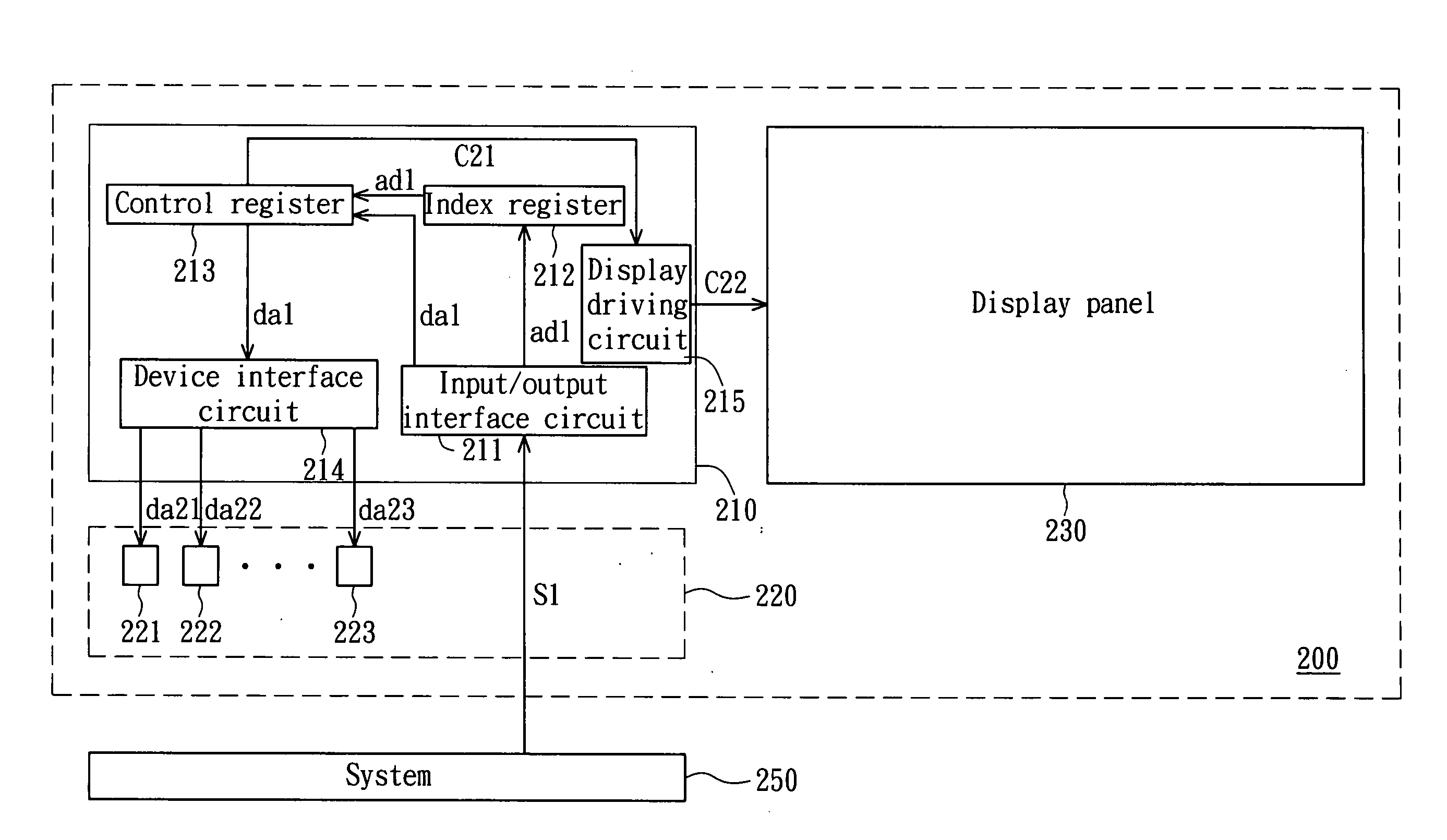
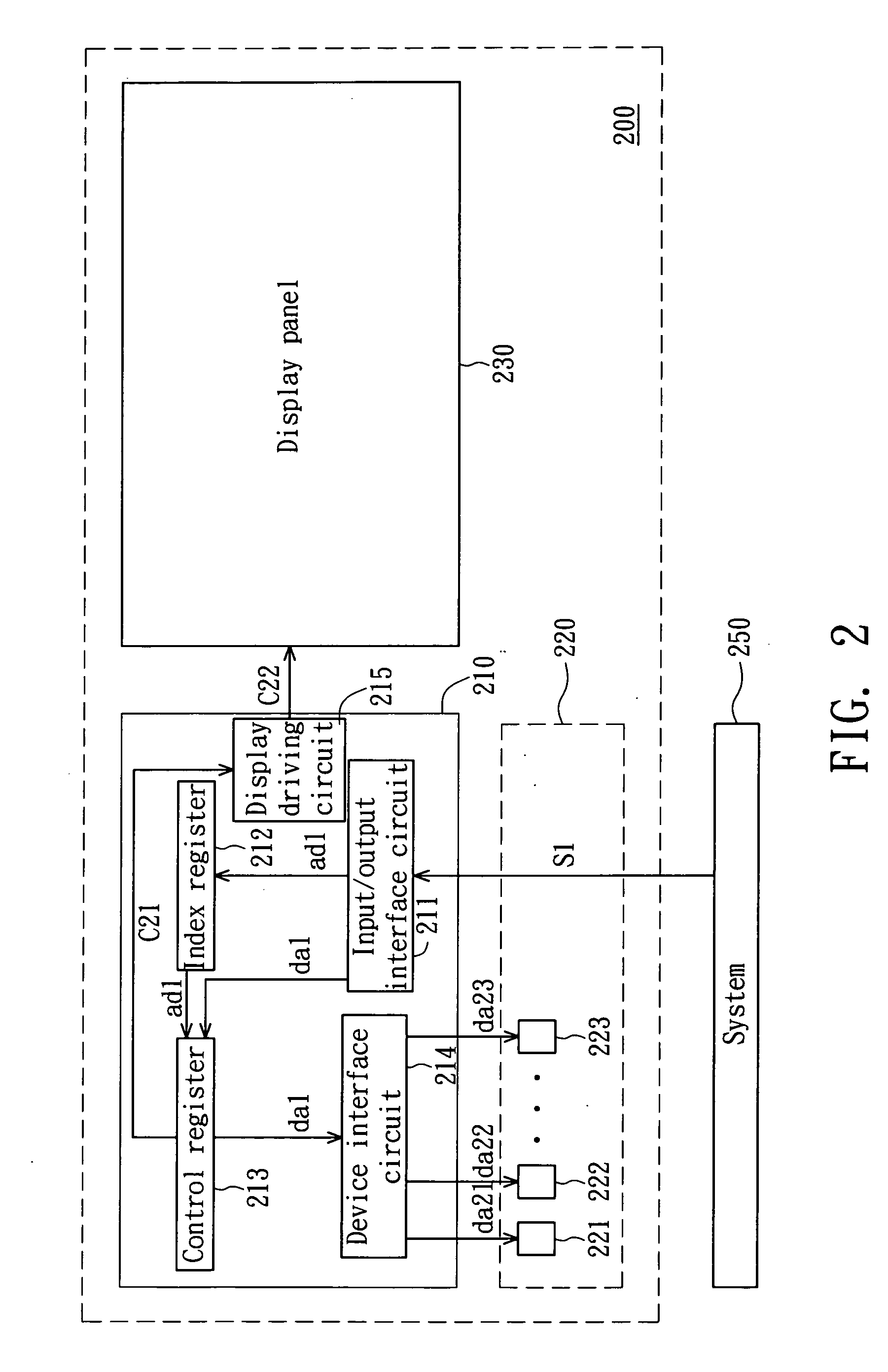
[0021]FIG. 2 is a block diagram showing a display module according to a preferred embodiment of the invention. Referring to FIG. 2, a display module 200 comprises a display panel 230, devices 221, 222 and 223 and a display driver IC 210. The display driver IC 210 receives a system signal S1, which is output from a system 250, to drive the display panel 230 and the devices 221 to 223. The display driver IC 210 in this embodiment is electrically connected to a display panel. In practice, however, the display driver IC may also be directly disposed on the display panel, such as a LTPS (Low Temperature Poly-Silicon) display panel.

[0022] The display driver IC 210 comprises an input / output interface circuit 211, an index register 212, a control register 213, a device interface circuit 214 and a display driving circuit 215. The input / output interface circuit 211 receives the system signal S1 and then outputs an address signal ad1 and a data signal da1 accordingly. The index register 212 e...


PUM


Abstract

A display driver IC and a driving method. The display driver IC is for receiving a system signal to drive a display panel or transmit data to a device. The display driver IC includes an input/output interface circuit, an index register, a control register and a device interface circuit. The input/output interface circuit receives the system signal and then outputs a first address signal and a first data signal accordingly. The index register stores and outputs the first address signal. The control register stores the first data signal and outputs the first data signal according to the first address signal output from the index register. The device interface circuit generates a second data signal according to the first data signal and outputs the second data signal to the device.

Description


Claims


Application Information

Patent Timeline
Owner MORGAN STANLEY
Why Eureka
Try Eureka