Adsorbent housing with separated adsorption outflow and desorption inflow

a technology of adsorbent housing and adsorption outflow, which is applied in the direction of separation process, instrument, dispersed particle separation, etc., can solve the problems of increasing the dead-volume area and surface active site, not using extra devices and valves, and increasing cost and space. , to achieve the effect of reducing the use of extra devices

Active Publication Date: 2006-11-02
PERKINELMER U S LLC
View PDF5 Cites 29 Cited by
  • Summary
  • Abstract
  • Description
  • Claims
  • Application Information

AI Technical Summary

Benefits of technology

[0012] Accordingly, an object of the present invention is to provide a system for pre-concentrating analytes in a sample prior to introduc

Problems solved by technology

However, to date, these systems have resulted in a number of disadvantages.
First, in order to accomplish this multiple stage process of extracting and transferring a sample fluid to the trap, trapping it and untrapping it, and transferring it to the chromatographic column, these systems have employed complex assemblies of parts and/or valves situated in the flow path of the fluid containing the analytes to be measured.
These extra devices and valves not only increase cost and space, but increase dead-volume areas and surface active sites.
This results in sample dispersion, dilution, or loss, and causes excessive peak broadening on the chromatogram.
Another disadvantage present in some of these systems is the u

Method used


Image

  • Adsorbent housing with separated adsorption outflow and desorption inflow
  • Adsorbent housing with separated adsorption outflow and desorption inflow
  • Adsorbent housing with separated adsorption outflow and desorption inflow

Examples


Embodiment Construction

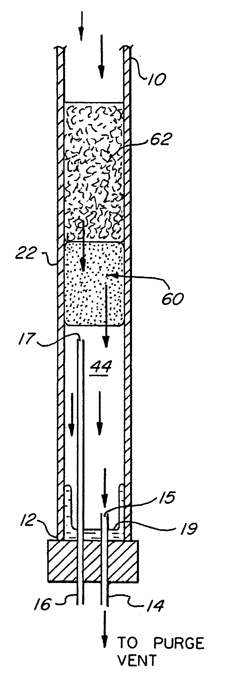
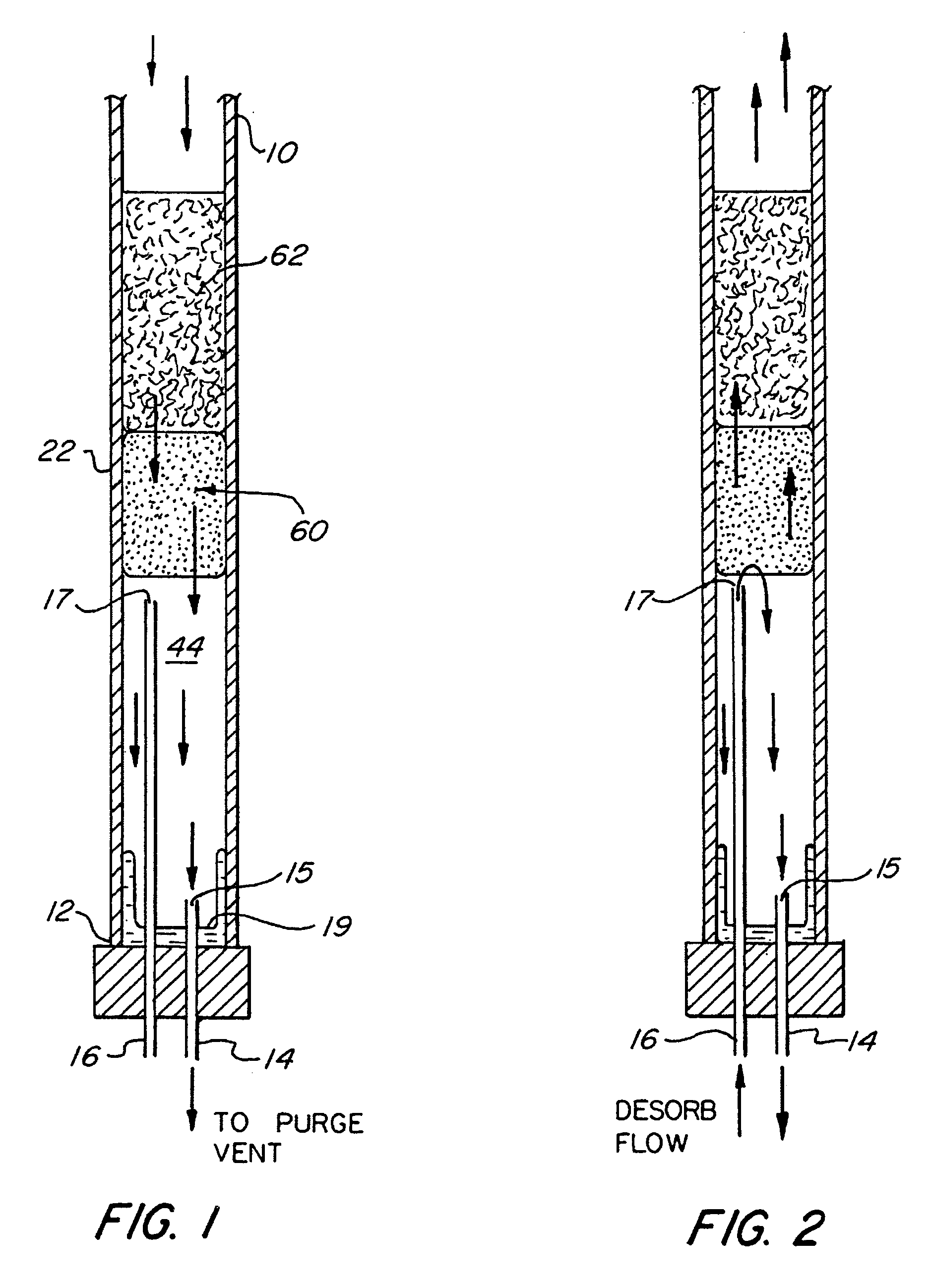
[0028] The basic components of one embodiment of an analyte pre-concentrator in accordance with the invention are illustrated in FIG. 1. As used in the description, the terms “top,”“bottom,”“above,”“below,”“over,”“under,”“above,”“beneath,”“on top,”“underneath,”“up,”“down,”“upper,”“lower,”“front,”“rear,”“back,”“forward” and “backward” refer to the objects referenced when in the orientation illustrated in the drawings, which orientation is not necessary for achieving the objects of the invention.

[0029] An adsorbent housing 22 includes a first end 10 for receiving a sample in any of a variety of ways, an example of which is further described below. The housing, which is typically a tube or liner of some sort, also has a second end 12, as well as a flow channel 44 therein. At least one adsorbent 60 is disposed in the flow channel 44 in order to adsorb the analytes in the sample as the sample fluid passes through the first end 10 and down into the flow channel 44. In certain advantageou...


PUM


Abstract

A system for pre-concentrating analytes in a sample prior to introduction into a chromatographic column is generally disclosed comprising a housing, an adsorbent disposed in the housing, and first and second conduits having an inlet and an outlet, respectively, for transferring fluid out of and into the housing during adsorption/dry purge and desorption stages, respectively. In some embodiments, the inlet of the first conduit and the outlet of the second conduit are both disposed in one end of the housing and are offset from each other with respect to the adsorbent.

Description

PRIOR APPLICATION [0001] The present application is a continuation of International Patent Application No. PCT / US2004 / 035371, filed Oct. 21, 2004, which designates the United States, and which claims priority benefits under 35 U.S.C. §119(e) of U.S. Provisional Patent Application Ser. No. 60 / 481,549, filed Oct. 23, 2003.FIELD OF THE INVENTION [0002] The present invention relates to a system for pre-concentrating analytes in chromatography. More specifically, the invention relates to an analyte pre-concentrator for minimizing the amount of moisture desorbed into a chromatographic column. BACKGROUND OF THE INVENTION [0003] Gas chromatography is essentially a physical method of separation in which constituents of a test sample in a carrier gas or liquid are adsorbed or absorbed and then desorbed by a stationary phase material into a column. A pulse of the sample is introduced into a steady flow of carrier gas, which carries the sample into the chromatographic column. The inside of the ...

Claims


Application Information

Patent Timeline
IPC IPC(8): G01N30/02G01N1/22G01N30/12
CPCG01N30/08G01N30/12G01N2030/143G01N2030/127G01N2030/121G01N2030/085G01N2030/025G01N2001/2229G01N30/40G01N2030/405G01N30/10
Inventor TIPLER, ANDREWEDWARDS, RICHARD G.BOTELHO, JAMES E.
Owner PERKINELMER U S LLC
Why Eureka
Try Eureka