
Flanged occlusion devices and methods

a technology of occlusion device and occlusion device, which is applied in the field of implantable medical devices, can solve the problems of not being able to address physiological conditions, not being able and/or advisable, and not being able to occlusion the left atrial appendage by surgical techniques, etc., and being unable and/or advisable to achieve the effect of reducing the risk of occlusion

Active Publication Date: 2006-11-02
ST JUDE MEDICAL CARDILOGY DIV INC
View PDF17 Cites 352 Cited by
  • Summary
  • Abstract
  • Description
  • Claims
  • Application Information

AI Technical Summary

Benefits of technology

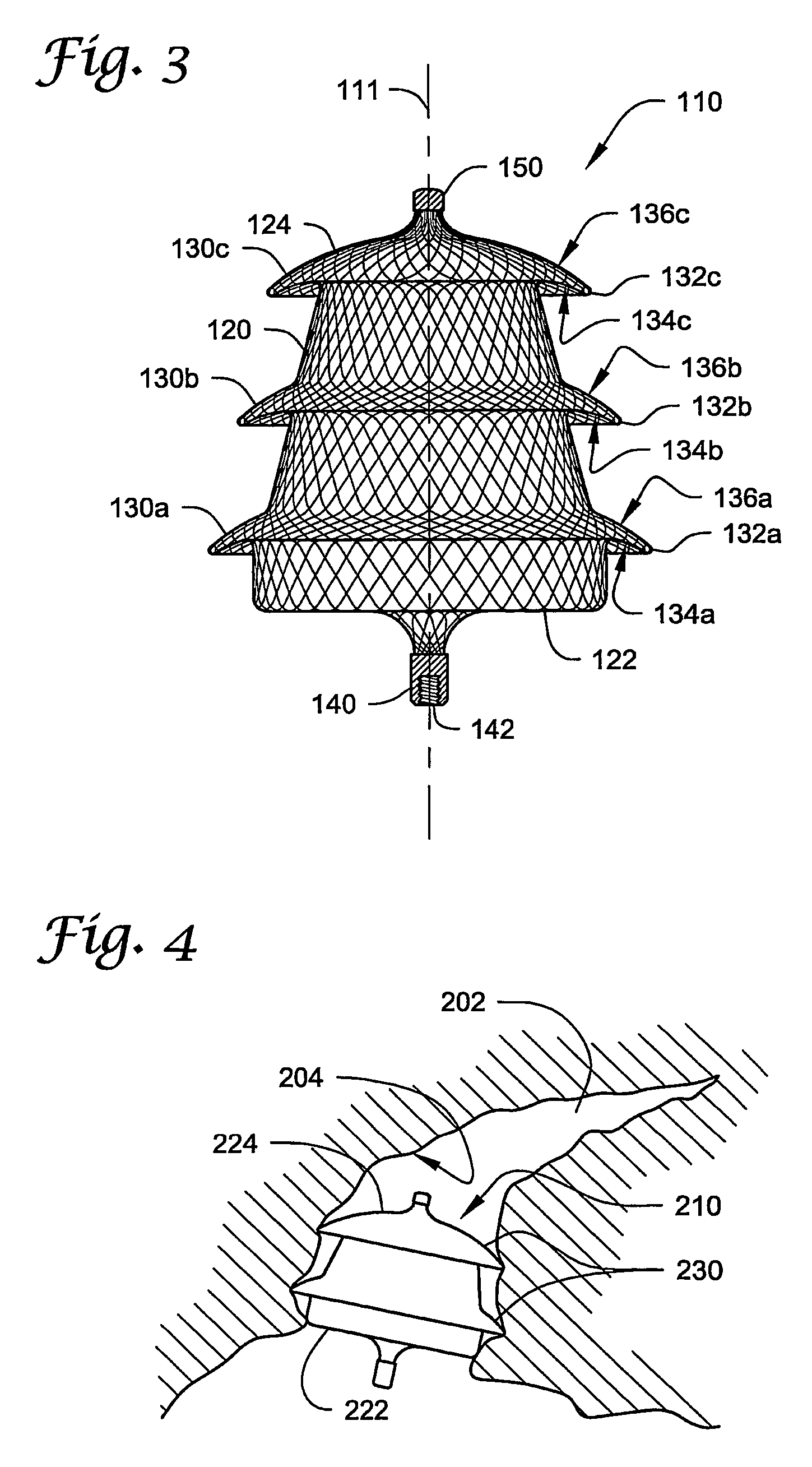
[0005] The present invention provides implantable occlusion devices that include one or more flanges extending from a tubular body. The flange or flanges may assist in retention of the device within a vessel, cavity, appendage, etc.
[0011] If the occlusion devices are manufactured by a braided tubular structure, the pick of the fabric forming the devices may preferably be increased from those described in connection with the devices described in the patents identified herein. “Pick” is defined as the number of turns per unit length for braided tubular structures. For example, it may be preferred that the pick be as high as 144 per lineal inch (approximately 55 per centimeter) or higher. Alternatively, the pick may be lower if so desired. In some embodiments, it may be preferred to incorporate a fabric or other structure within or on the occlusion devices (if, e.g., a lower pick is used) to enhance the ability of the occlusion device to collect thrombi and provide the occlusive properties desired.

Problems solved by technology

The devices described in the above-identified patents may not, however, be well-suited to address physiological conditions such as, e.g., occlusion of the left atrial appendage (LAA) to reduce the risk of embolisms when the left atrial appendage is undergoing atrial fibrillation.
Occlusion of the left atrial appendage by surgical techniques, while possible, is not always possible and / or advisable.
Furthermore, although some of the devices described in the above-identified patents may be used to occlude the left atrial appendage, they may be undesirably expelled from the left atrial appendage due to, e.g., forces generated by atrial fibrillation.

Method used


Image

  • Flanged occlusion devices and methods
  • Flanged occlusion devices and methods
  • Flanged occlusion devices and methods

Examples


Embodiment Construction

[0024] In the following detailed description of some exemplary embodiments of the invention, reference is made to the accompanying figures which form a part hereof, and in which are shown, by way of illustration, specific embodiments in which the invention may be practiced. It is to be understood that other embodiments may be utilized and structural changes may be made without departing from the scope of the present invention.

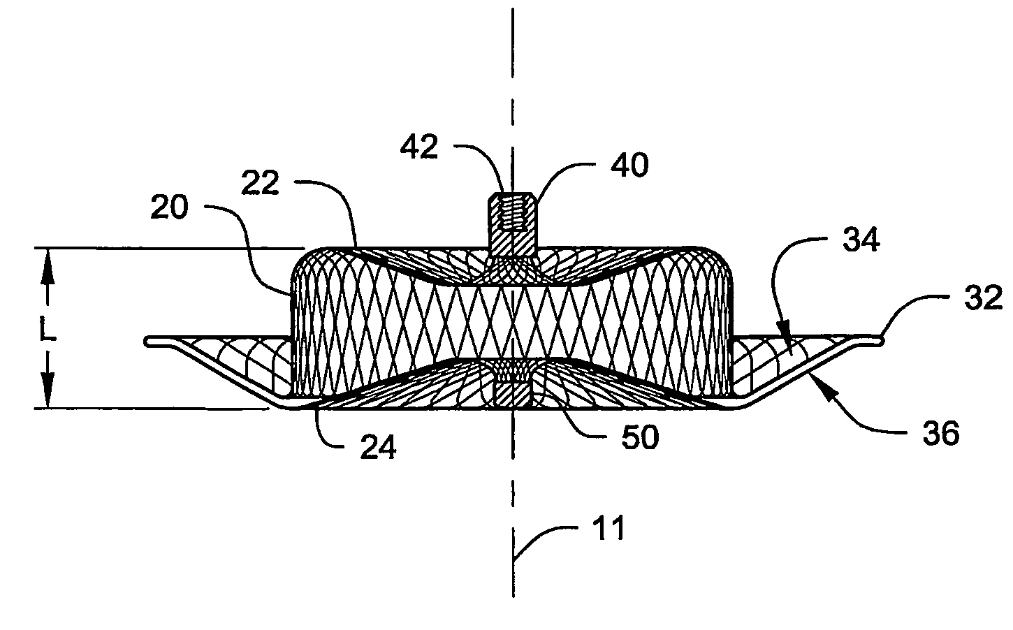
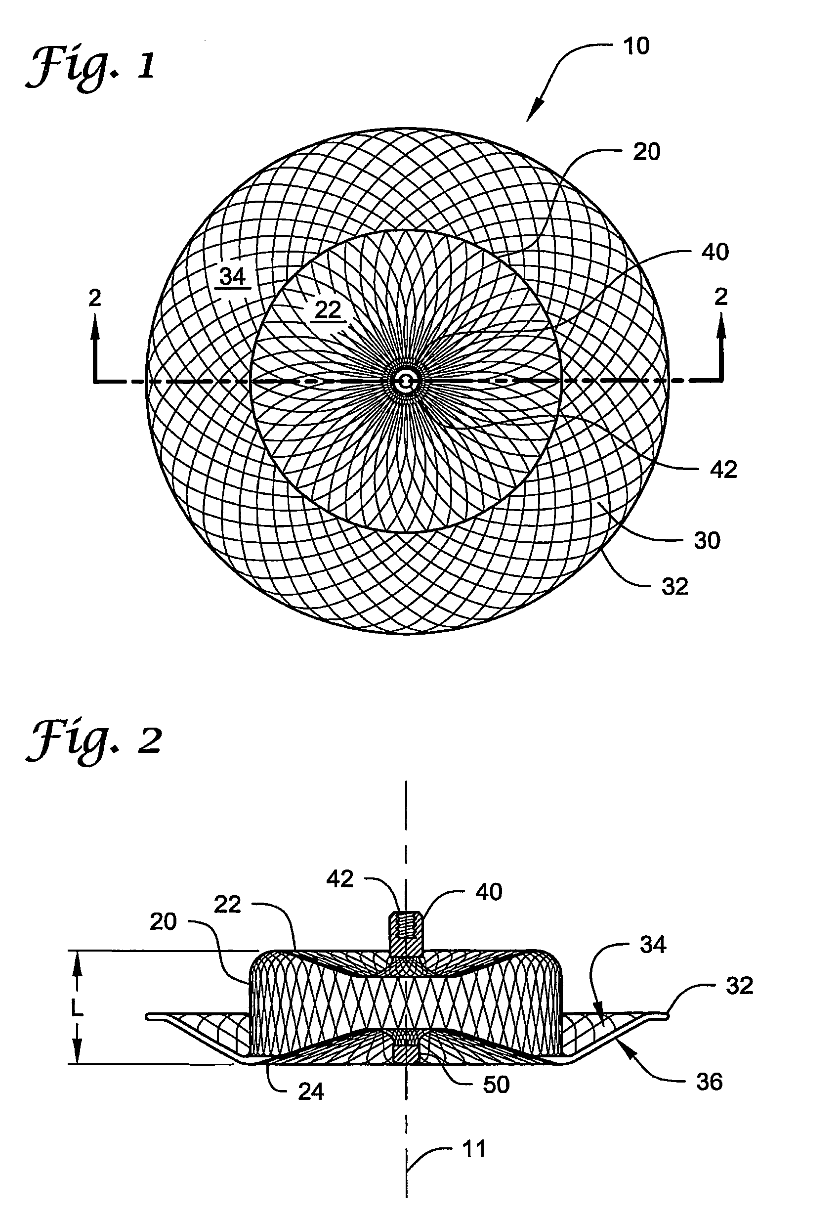
[0025]FIG. 1 is a plan view of one exemplary medical device according to the present invention (with the view taken along the longitudinal axis seen in FIG. 2) and FIG. 2 is a cross-sectional view of the device 10 taken along line 2-2 in FIG. 2. It may be preferred that the device 10 be constructed of a porous material (such as, e.g., a woven or braided fabric of strands—e.g., metallic strands), such that the device 10 includes openings between its exterior and preferably generally hollow interior volume.

[0026] Furthermore, the device 10 is depicted in its ex...


PUM


Abstract

Implantable occlusion devices that include one or more flanges extending from a tubular body are disclosed. The flange or flanges may assist in retention of the device within a vessel, cavity, appendage, etc. At least one flange on the occlusion device may include a concave surface proximate one end of a body. Because of the shape of the flange, e.g., its concavity, the occlusion device may resist dislocation due to e.g., the forces generated within the left atrial appendage during atrial filbrillation.

Description

RELATED APPLICATION [0001] This application claims the benefit of U.S. Provisional Patent Application No. 60 / 560,825 filed on Apr. 8, 2004, and titled OCCLUSION DEVICE WITH FLANGE AND METHODS, which is hereby incorporated by reference in its entirety.[0002] The present invention relates to the field of implantable medical devices, more particularly to implantable medical devices designed to occlude vessels, cavities, appendages, etc. within a body. [0003] A variety of devices and / or techniques have been developed to occlude a vessel or an opening in an organ (e.g., heart) of a patient. U.S. Pat. No. 5,725,552 (Kotula et al.); U.S. Pat. No. 5,846,261 (Kotula et al.); U.S. Pat. No. 5,944,738 (Amplatz et al.); U.S. Pat. No. 6,123,715 (Amplatz et al.); U.S. Pat. No. 6,368,339 B1 (Amplatz); U.S. Pat. No. 6,447,531 B1 (Amplatz); U.S. Pat. No. 6,579,303 B2 (Amplatz); U.S. Pat. No. 6,599,308 (Amplatz), etc. describe a variety of different devices that may be capable of achieving the desired...

Claims


Application Information

Patent Timeline
Patent Type & Authority Applications(United States)
IPC IPC(8): A61B17/08A61B17/00A61B17/12
CPCA61B17/0057A61B17/12022A61B17/12122A61B17/12172A61B2017/00632A61B2017/00575A61B2017/00592A61B2017/00615A61B2017/00243A61B17/12A61B17/122
Inventor AMPLATZ, KURTTHILL, GARY A.RUSSO, PATGU, XIAOPINGSANTER, JANA
Owner ST JUDE MEDICAL CARDILOGY DIV INC
Learn More