Soffit assembly for moveable wall system and removal tool therefor
a technology for moving walls and soffits, which is applied in the direction of walls, doors/window fittings, wing accessories, etc., can solve the problems of time-consuming installation and removal of screws and bolts, negating the primary purpose of soffits, and unappealing to the eye, so as to achieve quick and easy installation and assembly. the effect of easy assembly
- Summary
- Abstract
- Description
- Claims
- Application Information
AI Technical Summary
Benefits of technology
Problems solved by technology
Method used
Image
Examples
first embodiment
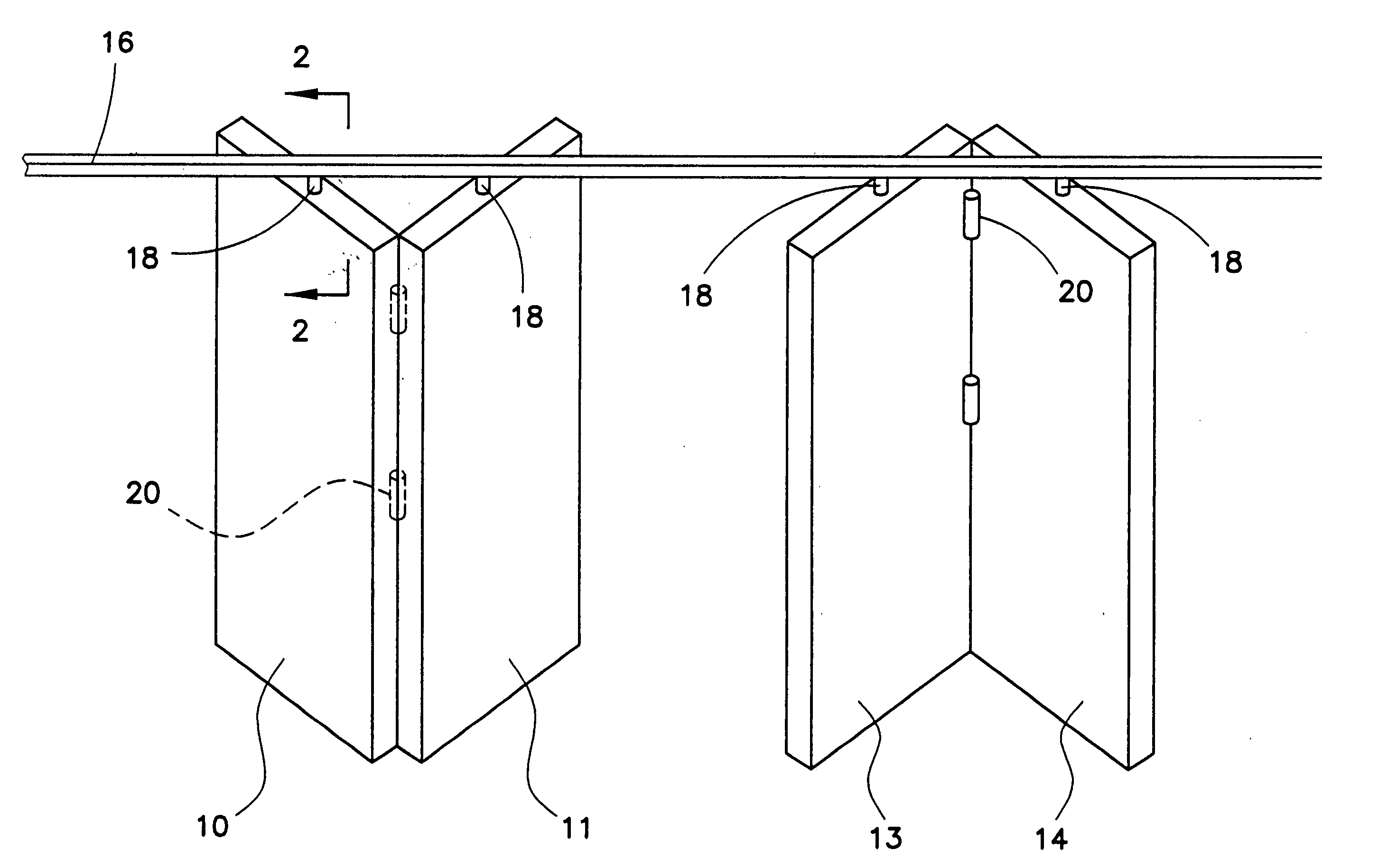
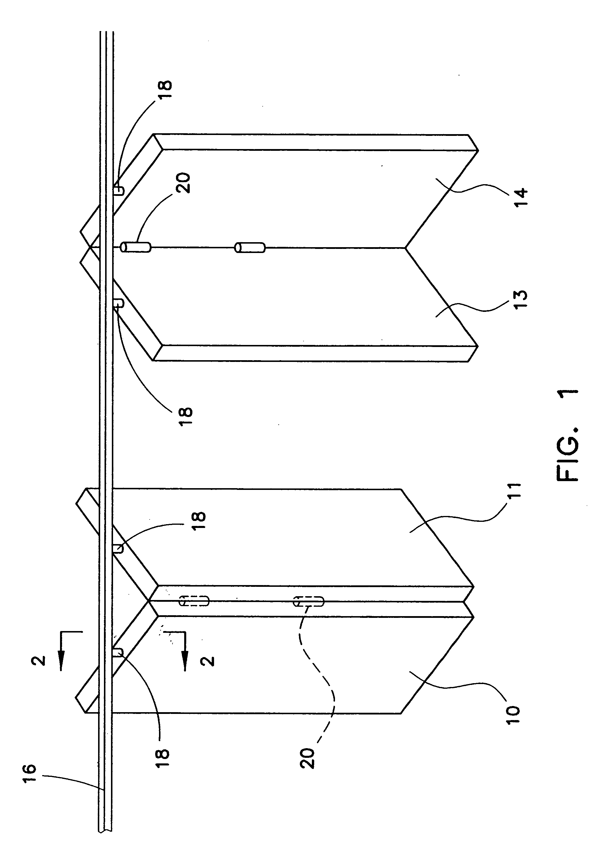
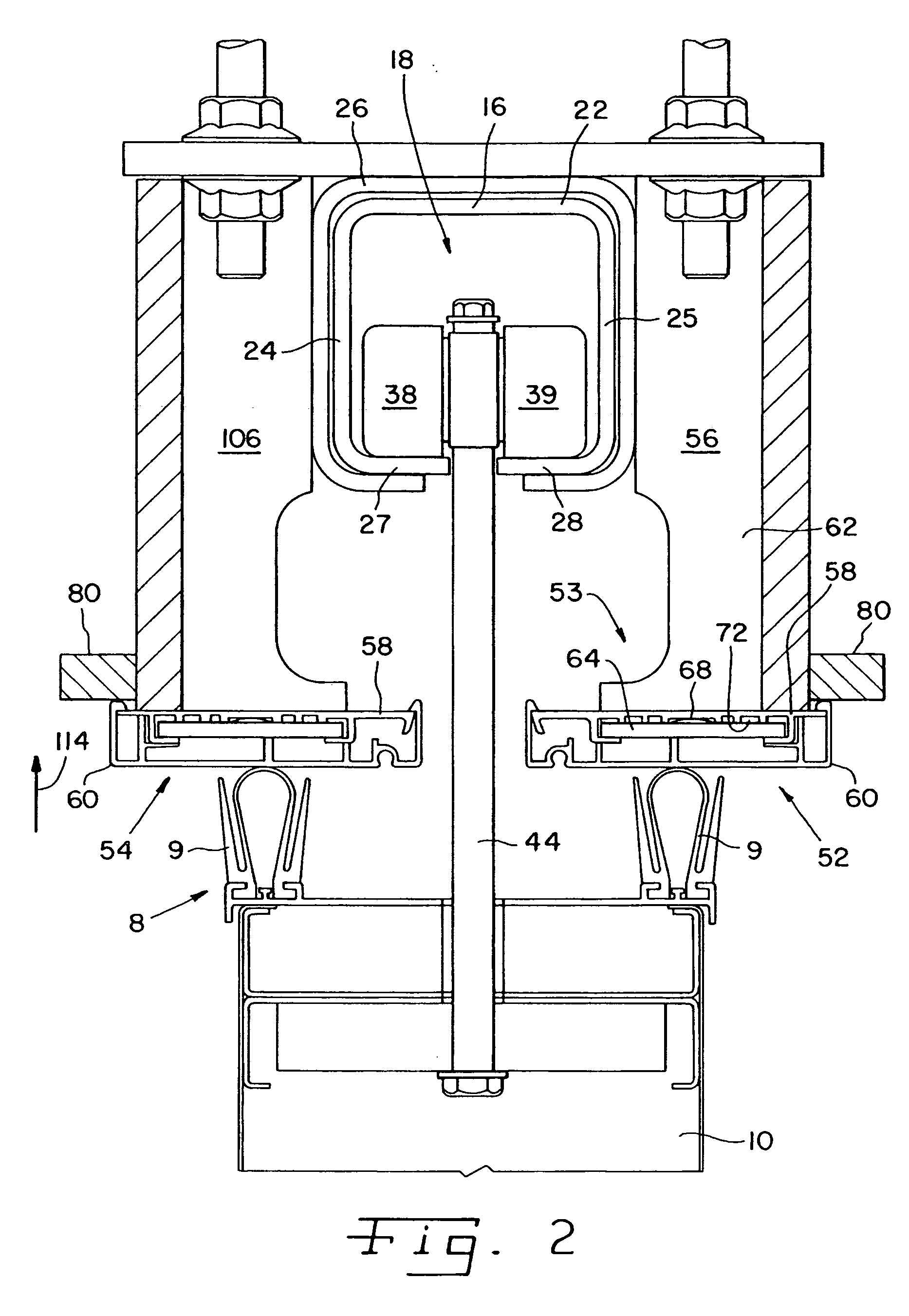
[0026] With reference now to FIGS. 2-4, one configuration of the track, trolley and a soffit assembly of the present invention is further described. Track 16 is of a known design and is made of hardened cold-rolled steel in a generally square tubed shape including a top wall 22, vertical side walls 24 and 25, and bottom wall portions 27 and 28. Track 16 may be mounted to the ceiling support structure by any means known in the art, such as by hanger brackets 26, one of which is shown in FIG. 2. Hanger brackets 26 may be positioned at spaced intervals along the length of the track. For example, in one embodiment, hanger brackets 26 are each approximately 5 inches long in a direction into the page of FIG. 2 and are provided at 24 inch intervals along the length of track 16.
[0027] The upper surfaces of bottom wall portions 27 and 28 are the surfaces along which the wheels of trolley 18 roll when the wall panel is moved. The inward facing edges of bottom wall portions 27 and 28 are horiz...
second embodiment
[0038] Referring now to FIG. 5A, there is shown a soffit assembly 152 of a movable wall system of the present invention. Track 116 may be part of an arcuate switch section of a movable wall system rather than a linear track section as shown in the embodiment of FIGS. 1-2. Because the track may curve in the switch section, and a curving square tube track may be difficult to manufacture, track 116 may not have a square tube design. Rather, track 116 may be planar with flat track sections 127, 128. The trolley is not shown in FIG. 5A, but trolley 18 may be suitable for use in the embodiment of FIG. 5A. Track 116 may be mounted to the ceiling support structure by bolts 120. Bolts 120 also mount soffit assemblies 152, 154 to track sections 127, 128.
[0039] Soffit assembly 152 includes a soffit attachment device 153 and a soffit 160. Soffit attachment device 153 includes a first portion in the form of a U-shaped soffit bracket 156 and a second portion in the form of a soffit clip 158.
[004...
PUM
 Abstract
Description
Claims
Application Information
 - R&D
- Intellectual Property
- Life Sciences
- Materials
- Tech Scout
- Unparalleled Data Quality
- Higher Quality Content
- 60% Fewer Hallucinations
Browse by: Latest US Patents, China's latest patents, Technical Efficacy Thesaurus, Application Domain, Technology Topic, Popular Technical Reports.
© 2025 PatSnap. All rights reserved.Legal|Privacy policy|Modern Slavery Act Transparency Statement|Sitemap|About US| Contact US: help@patsnap.com


