
Snare drum adjustable dampening device

a dampening device and adjustable technology, applied in the field of musical instruments, can solve the problems of often not very effective, usually structurally complex or cumbersome, etc., and achieve the effects of dampening the sounds, dampening the sounds, and dampening the sounds

Inactive Publication Date: 2006-11-09
REMO INC
View PDF2 Cites 7 Cited by
  • Summary
  • Abstract
  • Description
  • Claims
  • Application Information

AI Technical Summary

Benefits of technology

"The present invention provides an improved device for dampening the sounds produced by the drumhead of a musical drum. The device includes a frame assembly with two elongated bar members and mounting brackets for snare wires. A dampening means is also included, which can be adjusted to vary the tension of the wires against the drumhead. The device is easy to use, uncomplicated in structure, and relatively inexpensive to manufacture. The technical effects of the invention include the ability to adjust the tension of the snare wires and the dampening of the sounds produced by the drumhead."

Problems solved by technology

These devices, which are usually structurally complex or cumbersome and / or often not very effective, include, for example, the devices disclosed and claimed in U.S. Pat. No. 6,307,133; U.S. Pat. No. 6,586,664 and U.S. Pat. No. 6,091,010.

Method used


Image

  • Snare drum adjustable dampening device
  • Snare drum adjustable dampening device
  • Snare drum adjustable dampening device

Examples


Embodiment Construction

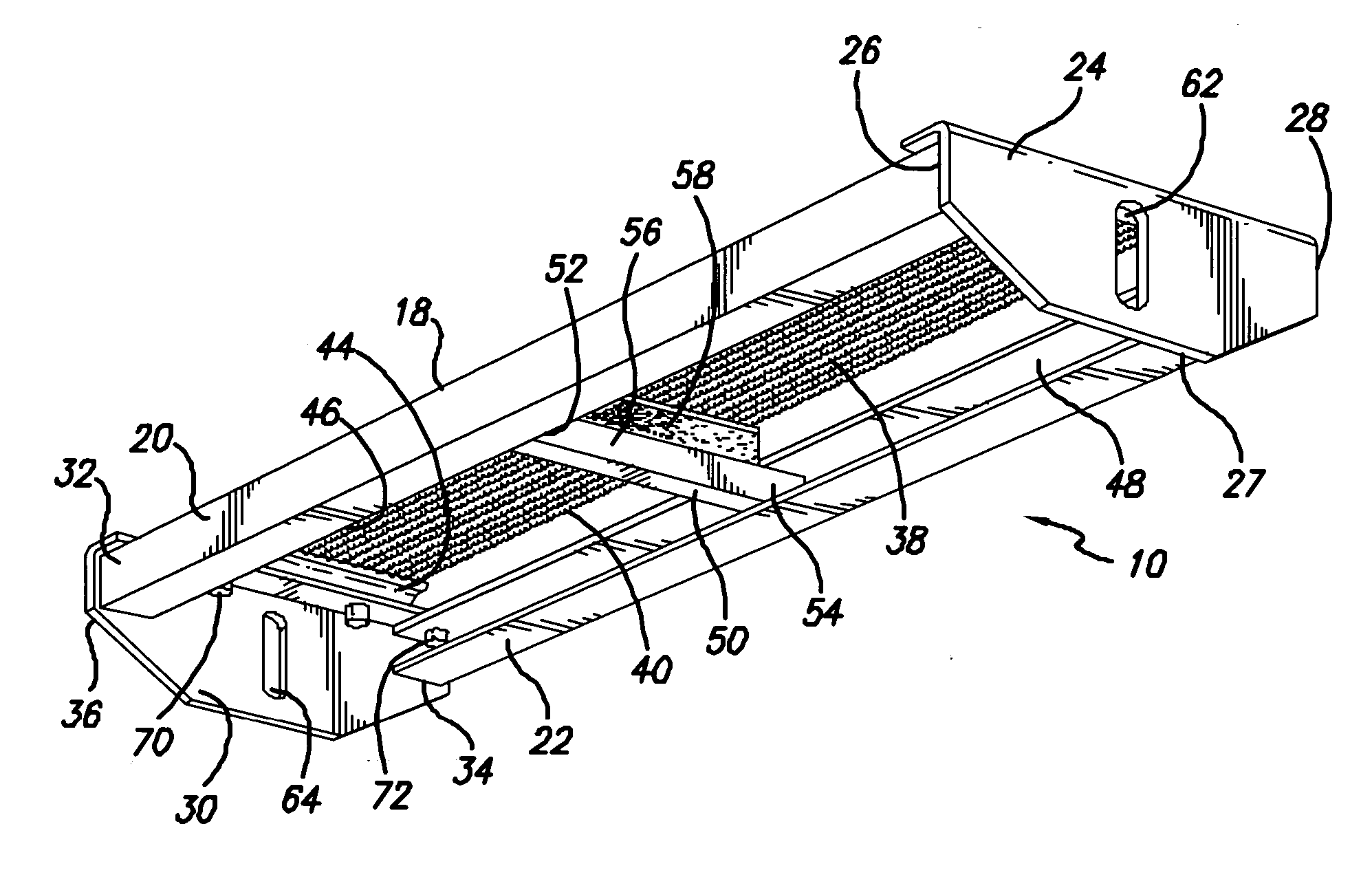
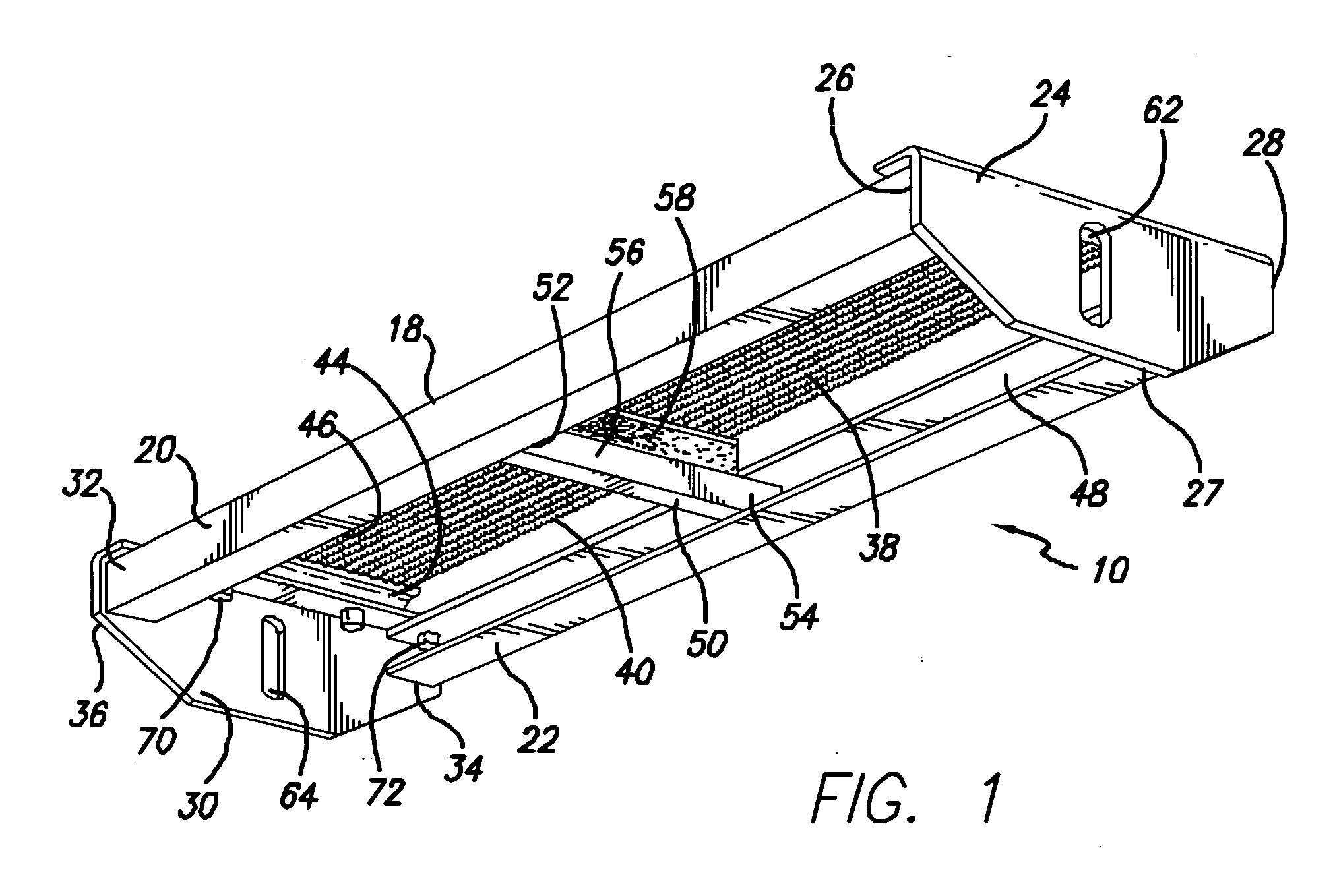
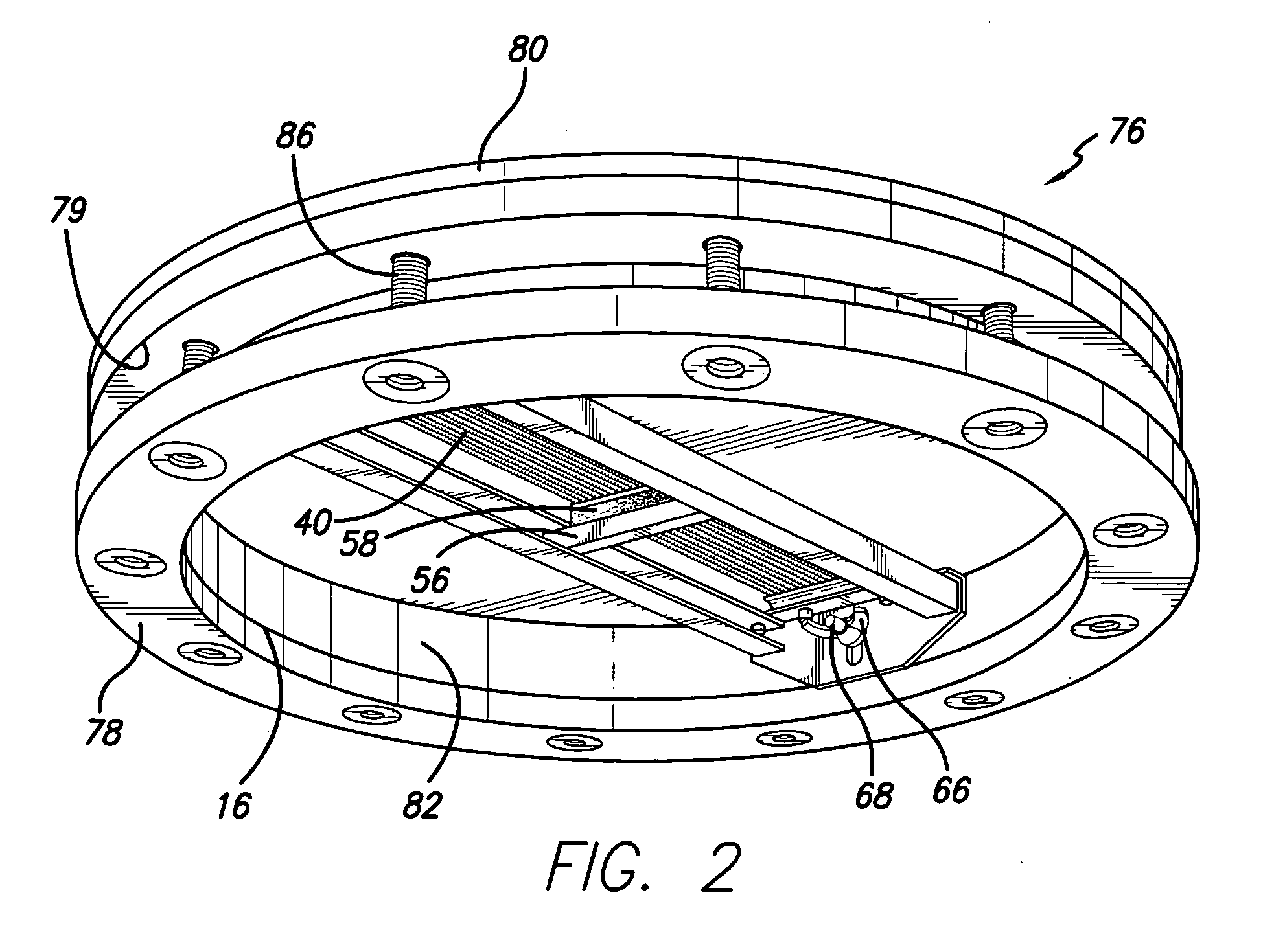
[0025] Referring more particularly to the drawings, FIG. 1 is a perspective view of the preferred embodiment of the present invention depicting a device 10 for dampening sounds produced by the drumhead 12 of a musical drum 14 having a drumshell 16, as shown in FIG. 3. Device 10 includes a frame assembly 18 having an elongated bar 20 on one side and an elongated bar 22 extending in opposed parallel relation on the other. Mounting bracket 24 is affixed to end 26 of bar 20 and end 27 of bar 22 at end 28 of frame assembly 18. Mounting bracket 30 is affixed to end 32 of bar 20 and end 34 of bar 22 at end 36 of frame assembly 18. Strands of wire 38, usually helical shaped, comprising snare 40 are positioned between bar 20 and bar 22 and secured to mounting brackets 24, 30 at end plates 42, 44, respectively. Formed within bars 20, 22 are elongated channels 46, 48, respectively, extending the entire length of each bar.

[0026] A dampening member 50 with ends 52, 54 adapted to fit slidably in...


PUM


Abstract

A device for dampening sounds produced by a drumhead of a musical drum having a drumshell comprising a frame assembly having a first elongated bar member with a first channel and a second elongated bar member with a second channel. The two bar members are disposed in opposed spaced apart parallel relation. Mounting brackets are affixed and secured to the two bar members at their opposing ends. Attached, respectively, to the two mounting brackets between the two bar members are the opposing ends of an assembly of snare wires. The mounting brackets are also provided to connect the assembly to the drumshell and are vertically adjustable between a high tension position such that the snare wires are moved to press against the drumhead and a lower tension position in which the wires are caused to relax to enable the release of tension of the wires against the drumhead. The dampening member has end components adapted to fit slidably into the first and second channels, respectively, to enable the dampening member to be movable between the two elongated bar members along the frame assembly in physical contact with the snare wires to adjust the tension of the wires against the drumhead to produce a variety of sounds. The dampening member is comprised of a base member, a device for physically contacting the snare wires as it is moved along the frame assembly and a resilient material situated between the base member and the contact device to buffer vibrations produced by the struck drumhead.

Description

BACKGROUND OF THE INVENTION [0001] 1. Field of the Invention [0002] The present invention relates generally to the field of musical instruments and, more particularly, to an improved device for dampening the sounds produced by the drumhead of a musical drum. [0003] 2. Description of the Prior Art [0004] Snare drums have unique characteristics that make them very different from a bass drum, tom-tom drum and various other conventional, modern and ethnic drums. Typical snare drums consists of a hollow body or shell with a drumhead covering either the top opening or both the top and bottom openings. The head that is struck by a drumstick or the like is called the batter head. Secured to the inside of the drumshell beneath the batter head is a snare assembly fashioned primarily of a plurality of wire strands held near or against the underside or inside surface of the batter head. [0005] In order to vary the sounds produced by snare drums, a variety of devices or assemblies are provided t...

Claims


Application Information

Patent Timeline
Patent Type & Authority Applications(United States)
IPC IPC(8): G10D13/02
CPCG10D13/025G10D13/022G10D13/14G10D13/02G10D13/18
Inventor WHITTINGTON, CHRISTOPHER JOESPHCAVALLARO, LOUIS CHARLES JR.
Owner REMO INC
Learn More