Carton and insert and blank for forming the same

a technology of inserts and blanks, applied in the field of cartons and blanks, to achieve the effect of more rigidity

Inactive Publication Date: 2006-11-09
MEADWESTVACO PACKAGING SYST LLC
View PDF32 Cites 35 Cited by
  • Summary
  • Abstract
  • Description
  • Claims
  • Application Information

AI Technical Summary

Benefits of technology

[0007] One advantage of this arrangement is that the insert structure is held in position adjacent the carton bottom. Holding the insert structure in this position is important to allow the insert structure to function as a cushion between the bottles. Beneficially, the amount of board used for the insert structure can be reduced and standard equipment to secure the end panels can be used to secure the insert structure to the outer carton.
[0013] An advantage with the preferred feature is that the insert structure is more rigid because the opposed transverse partition panels are secured together.

Problems solved by technology

In such known cartons, the insert is free to move in a vertical plane, which is undesirable because the insert will no longer serve as a cushion if moved in an upward position, for example between bottle necks.

Method used


Image

  • Carton and insert and blank for forming the same
  • Carton and insert and blank for forming the same
  • Carton and insert and blank for forming the same

Examples


first embodiment

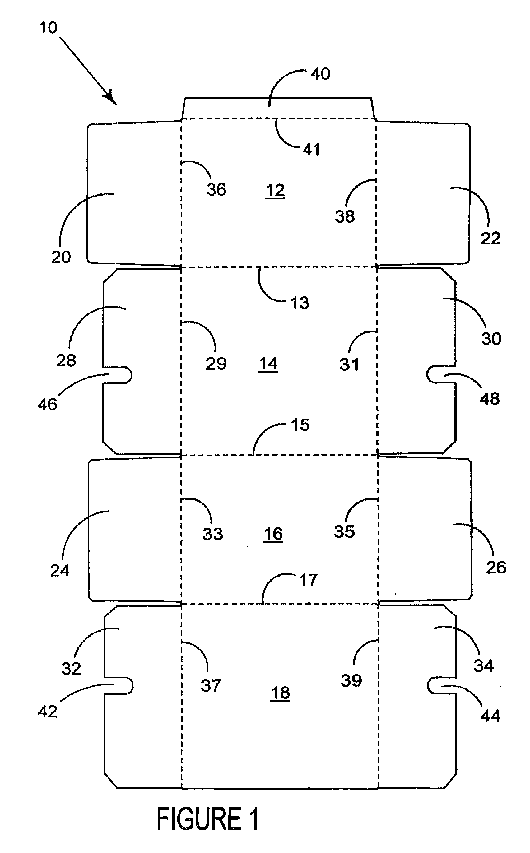
[0036] Turning to the first embodiment shown in FIG. 1, the blank 10 comprises a plurality of panels for forming the top, base and opposed side walls whereby there is shown a top panel 12, a first side wall panel 14, bottom panel 16 and second side wall panel 18 hingedly connected one to the next in series along fold lines 13, 15 and 17 respectively.

[0037] The ends of the carton are constructed by one or more end panels. In this embodiment, opposed end panels 20 and 22 are hingedly connected to the opposing ends of top wall panel 12 along fold lines 36 and 38 respectively. A second pair of end panels 24, 26 is provided along opposing end edges of base panel 16 and hingedly connected thereto along fold lines 36 and 38 respectively.

[0038] Preferably, a pair of end flaps 28, 30 is hingedly connected to first side wall panel 14 along opposing end edges and are connected thereto by fold lines 36, 38 respectively. Likewise, a second pair of end flaps 32, 34 are hingedly connected to side...

third embodiment

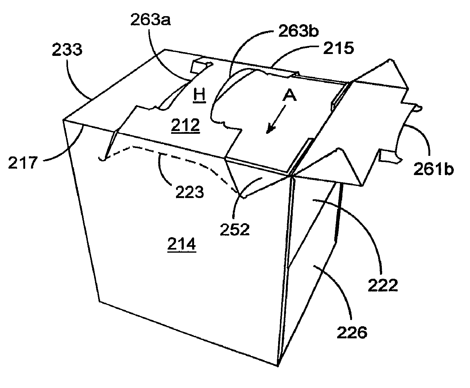
[0076] Turning to the third embodiment illustrated in FIG. 16, the outer carton is formed and loaded in an identical manner to that described above. In this embodiment, the insert structure is attached to the outer panels of the end walls at each end. This is achieved by the provision of flaps, 251 and 257 which appear through the recesses 242, 246, as shown in FIG. 17. Thereafter the end wall 226 is secured directly to one or both of panels 251, 257 by the application of glue in a standard method.

[0077] The handle is constructed when the user pushes the hand flaps inwardly to reveal the handle strip shown in FIG. 18. Lifting the handle strip will separate it from the top and side walls because of the cut lines 227, 229 and 261. The handle strip is hinged to the top panel 212 by step panels 267, which pivot about their hinged connections between the handle strip H and the side walls 218 and 214 to dissipate some of the load from lifting the handle.

[0078] In order to gain access to ...


PUM

PropertyMeasurementUnit
rigidityaaaaaaaaaa
shapeaaaaaaaaaa
areasaaaaaaaaaa

Abstract

A package and two part blank for forming a package for carrying one or more articles comprising a carton having a plurality of wall panels for forming a tubular structure wherein each end of the carton is closed by a first panel hingedly connected to one of the wall panels, an intermediate panel hingedly connected to another wall panel of the carton and adapted to be placed in face contacting relationship within the inner face of the first panel. There further comprises within the carton an insert structure for supporting the one or more articles including a second panel. An aperture or recess is provided in the intermediate panel such that glue applied to an outer face of the second panel and the intermediate panel secures together said first, second and intermediate panels when placed together in face contacting relationship to close the end of the carton.

Description

CROSS REFERENCE TO RELATED APPLICATIONS [0001] This application is a continuation of U.S. application Ser. No. 10 / 364,539, filed Feb. 10, 2003, which is a continuation of International Application No. PCT / US01 / 24698, filed Aug. 7, 2001, which claims priority to Great Britain Application No. 0017955.8, filed Aug. 10, 2000, the entirety of the above-identified applications are incorporated herein by reference.BACKGROUND OF THE INVENTION [0002] The invention relates to a carton and blank for forming a carton for carrying a plurality of articles and an insert structure associated with the carton to provide additional protection to articles contained in the carton. [0003] The use of an insert or partition in a carton is well known as a means to serve as a cushion between the articles and / or between the articles and the outer walls to protect them. In such known cartons, the insert is free to move in a vertical plane, which is undesirable because the insert will no longer serve as a cushi...

Claims


Application Information

Patent Timeline
Patent Type & Authority Applications(United States)
IPC IPC(8): B65D65/00B65D75/00B65D5/49B65D5/54B65D71/00B65D71/36
CPCB65D5/16B65D2571/0087B65D5/46192B65D5/48028B65D5/48036B65D5/5405B65D71/36B65D2571/00141B65D2571/0032B65D2571/00425B65D2571/00469B65D2571/00512B65D2571/00543B65D2571/00549B65D2571/00574B65D2571/0066B65D2571/00728B65D2571/00814B65D5/4204
Inventor AUCLAIR, JEAN-MICHELDANIEL, JEAN-YVES
Owner MEADWESTVACO PACKAGING SYST LLC
Why Eureka
Try Eureka