
Relay structure improvement

Inactive Publication Date: 2006-11-09
SONG CHUAN PRECISION
View PDF13 Cites 0 Cited by
  • Summary
  • Abstract
  • Description
  • Claims
  • Application Information

AI Technical Summary

Benefits of technology

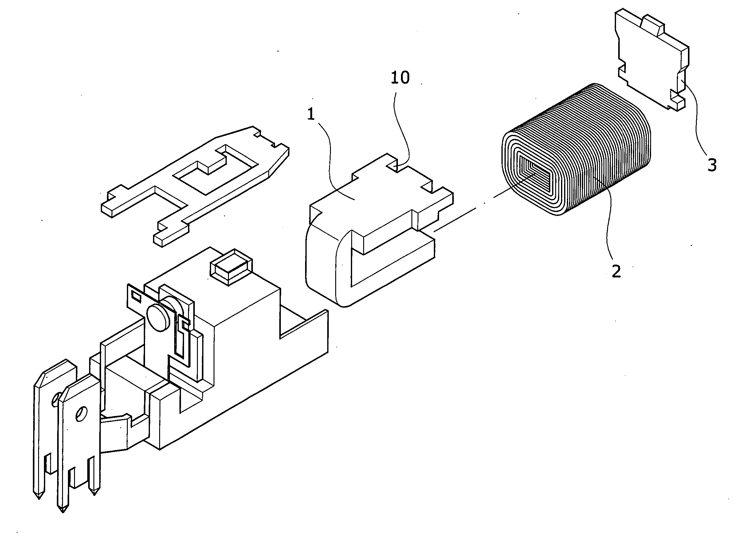
[0006] It is therefore a primary object of the present invention to provide an apparatus of “Relay Structure Improvement” by which magnetic beam can concentrate to produce better magnetic force, and resolve the voltage input problem of specific coil simultaneously to meet the most application requirements of a relay in the market.
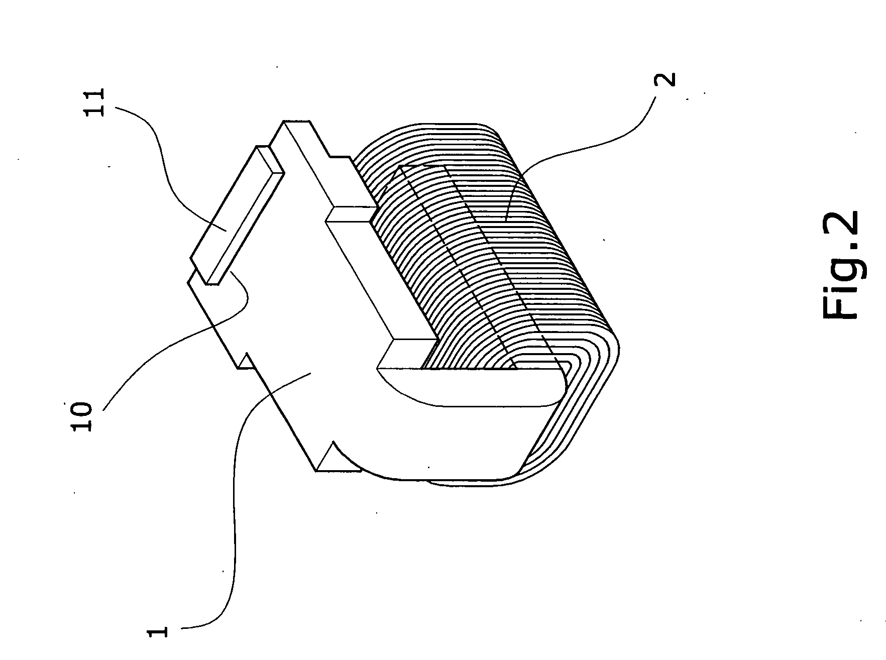
[0007] It is a further object of the present invention of “Relay Structure Improvement” that mainly consists of a edge-cut iron core which is characterized by: a coil winded around the outer edge of the edge-cut iron core, and a magnetic pole fitted at one end of the edge-cut iron core with a proper clearance arranged between magnetic pole and edge-cut iron core, and one or multiple edge-cut grooves arranged at the end that nears magnetic pole with a copper piece on it. According to the above-mentioned structure, the edge-cut grooves of the present invention of “Relay Structure Improvement” could alter the deployment of magnetic bean to attain better magnetic force which is proportion to the cross section area of the edge-cut grooves that can alter the deployment of magnetic force depending on the size of cross section area and resolve the voltage input problem of a specific coil to meet the market application requirements of a relay.

Problems solved by technology

Because the wave has zero voltage time, and the magnetic beam of normal conventional iron core is more dispersible and difficult to concentrate; then the phenomena causes the magnetic force of conventional direct current relay weaker, and could not absorb the magnetic pole in a steady way so as to set aside the poor performance and noisy sound, and bring product producer and user much annoyance.

Method used


Image

  • Relay structure improvement
  • Relay structure improvement
  • Relay structure improvement

Examples


Embodiment Construction

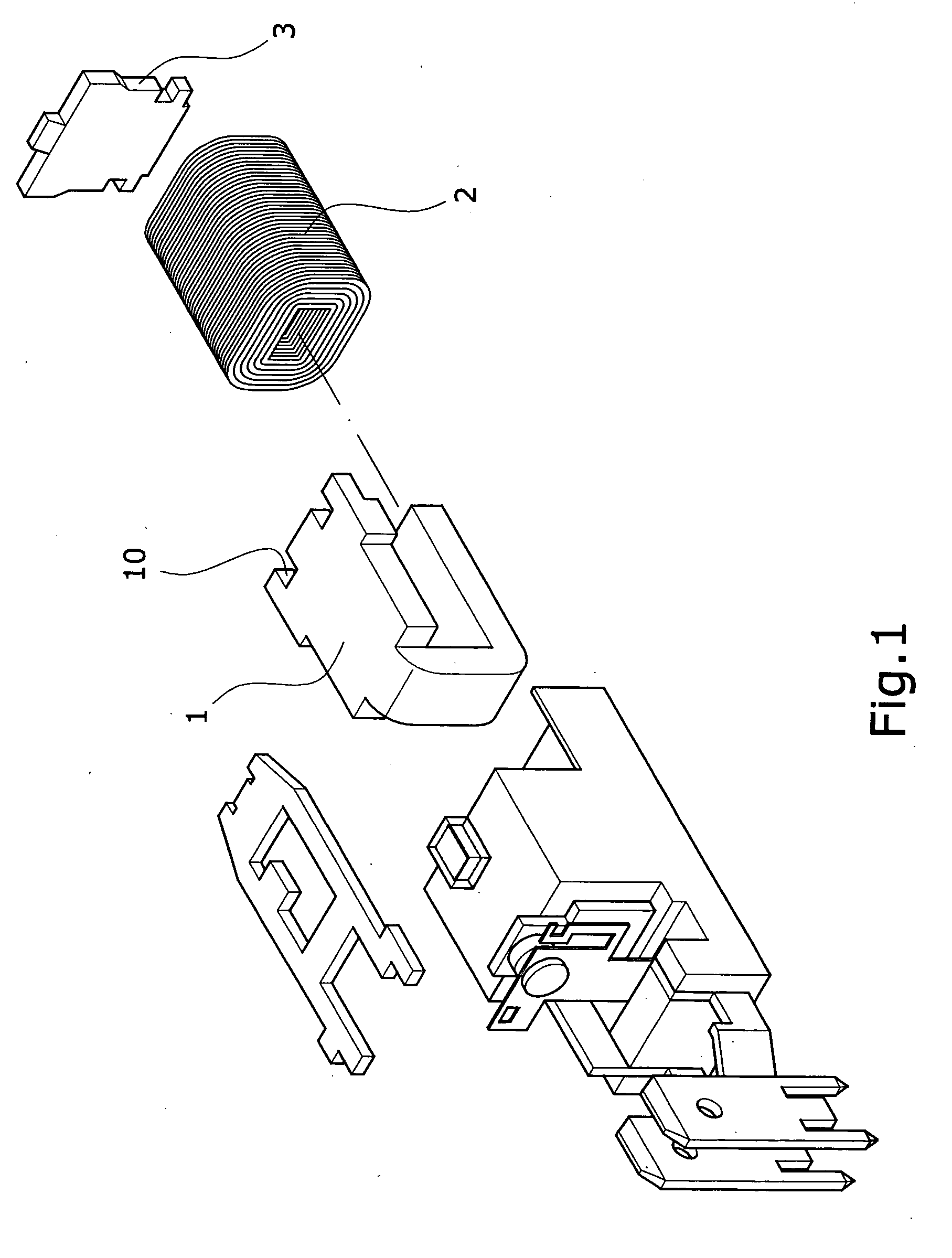
[0012] Referring to FIG. 1, 2, 3, 3A, the present invention of “Relay Structure Improvement” mainly consists of a edge-cut iron core 1 which is characterized by: a coil 2 winded around the outer edge of the edge-cut iron core 1, and a magnetic pole 3 fitted at one end of the edge-cut iron core 1 with a proper clearance arranged between magnetic pole 3 and edge-cut iron core 1, and one or multiple edge-cut grooves 10 arranged at the end that nears magnetic pole 3 fixes a copper piece 11 on it. Accordingly, the present invention of “Relay Structure Improvement” use a coil 2 and a magnetic pole 3 in a solid unit to replace with conventional iron core, edge-cut iron core 1 and edge-cut iron core 1 with copper piece 11 for input voltage examination; and the examination result shows that when apply voltage into the coil 2, the magnetic force of edge-cut iron core 1 without copper piece is stronger than that of conventional iron core by the reason of the edge-cut groove 10 altering the dep...


PUM


Abstract

A relay structure includes an iron core which is winded by a coil at one end and arranged an armature at the other end with proper clearance from the iron core, and one or multiple grooves. According to the structure, the grooves can alter the deployment of the magnetic beam, attain a better magnetic force, and resolve the problem of voltage input of a specific coil to meet the most application requirements from a relay in the market.

Description

BACKGROUND OF THE INVENTION [0001] I. Field of the Invention [0002] The present invention relates to a device of “Relay Structure Improvement”, more particularly to an apparatus, which can alter the deployment of magnetic beam to attain better magnetic force and resolve the voltage input problem of a specific coil to meet the most application requirement a relay in the current market can provide. [0003] II. Description of the Prior Art [0004] Relay is a kind of control apparatus in our daily life; as usual we name it as switch to fulfill some conditional terms. It is heavily used in many control system, especially those discrete control system. From another viewpoint, an electric circuits for some functional purpose more often than not needs to combine with some other mechanical components for complete performance; in the situation relay plays a role as interface between electric components and mechanical components. [0005] Furthermore, most of conventional electronic appliance rece...

Claims


Application Information

Patent Timeline
IPC IPC(8): H01H67/02
CPCH01F7/081H01H50/36H01F7/1638
Inventor WU, SUNG-JEN
Owner SONG CHUAN PRECISION
Learn More