
Mask Holding Device Capable of Changing Magnetic Means and Deposition Equipment Using the Same

a technology of magnetic means and masks, applied in the direction of spray discharge apparatus, vacuum evaporation coating, coating, etc., can solve the problems of inability to properly attach inability to apply the magnetic force, and inability to properly fix the mask to the substrate, so as to prevent the mask from deformation and precise and reliable deposition

Active Publication Date: 2012-08-16
SAMSUNG DISPLAY CO LTD
View PDF3 Cites 30 Cited by
  • Summary
  • Abstract
  • Description
  • Claims
  • Application Information

AI Technical Summary

Benefits of technology

[0017]In addition, the present invention provides a mask holding device using a permanent magnet, in which the permanent magnet can be easily replaced.
[0019]Finally, the present invention provides a deposition apparatus in which a permanent magnet can be replaced without releasing the vacuum state of the deposition apparatus.
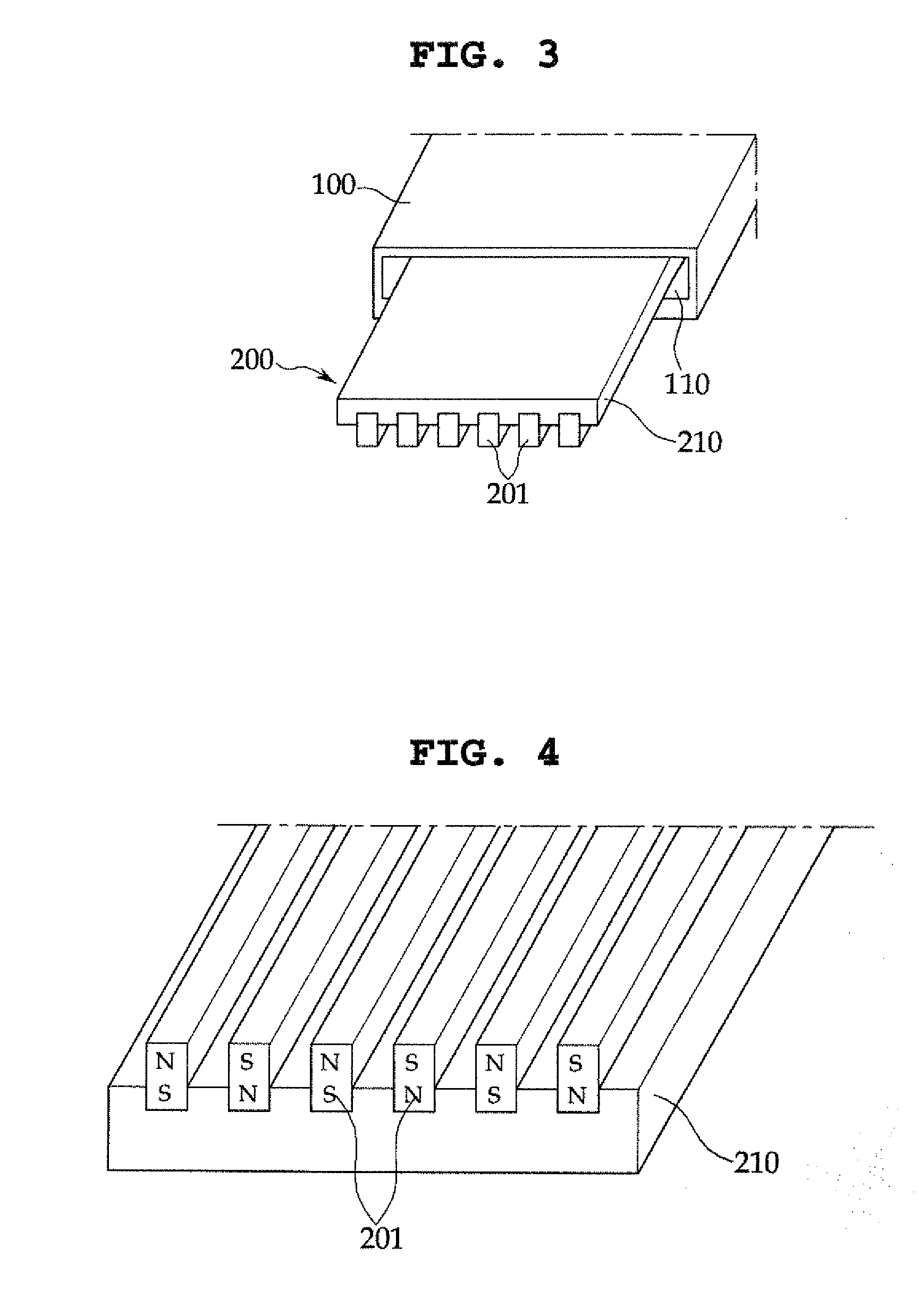
[0033]The mask holding device and the deposition apparatus, according to the present invention, include a magnetic means, in which magnets disposed in the magnetic means can be replaced. Thus, it is possible to supply an optimum magnetic force according to the size, the resolution, the type, and the material of a mask.
[0034]When the deposition apparatus according to the present invention is used, an optimum magnetic force corresponding to the size, the resolution, the type and the material of a mask is supplied. Thus, it is possible to prevent the mask from being deformed by the magnetic force while tightly attaching the mask to the substrate. This allows precise and reliable deposition to be carried out.

Problems solved by technology

In such a conventional deposition apparatus employing a magnetic fixing method, in some cases, an appropriate magnetic force required for the size and the material of the mask and the substrate cannot be applied for fixing the mask on the substrate.
For example, when an excessively high magnetic force is used to bring the mask into contact with the substrate, wiring or barriers, which are formed in the substrate by photoresist or the like, may be damaged by an effect of the magnetic field.
On the other hand, when a magnetic force is weaker than needed, it is impossible to properly attach the mask to the substrate.
Such vacuum-releasing and opening of the chamber may result in a great loss in view of a deposition process.

Method used


Image

  • Mask Holding Device Capable of Changing Magnetic Means and Deposition Equipment Using the Same
  • Mask Holding Device Capable of Changing Magnetic Means and Deposition Equipment Using the Same
  • Mask Holding Device Capable of Changing Magnetic Means and Deposition Equipment Using the Same

Examples


Embodiment Construction

[0044]Hereinafter, the present invention will be described in more detail with reference to the accompanying drawings.

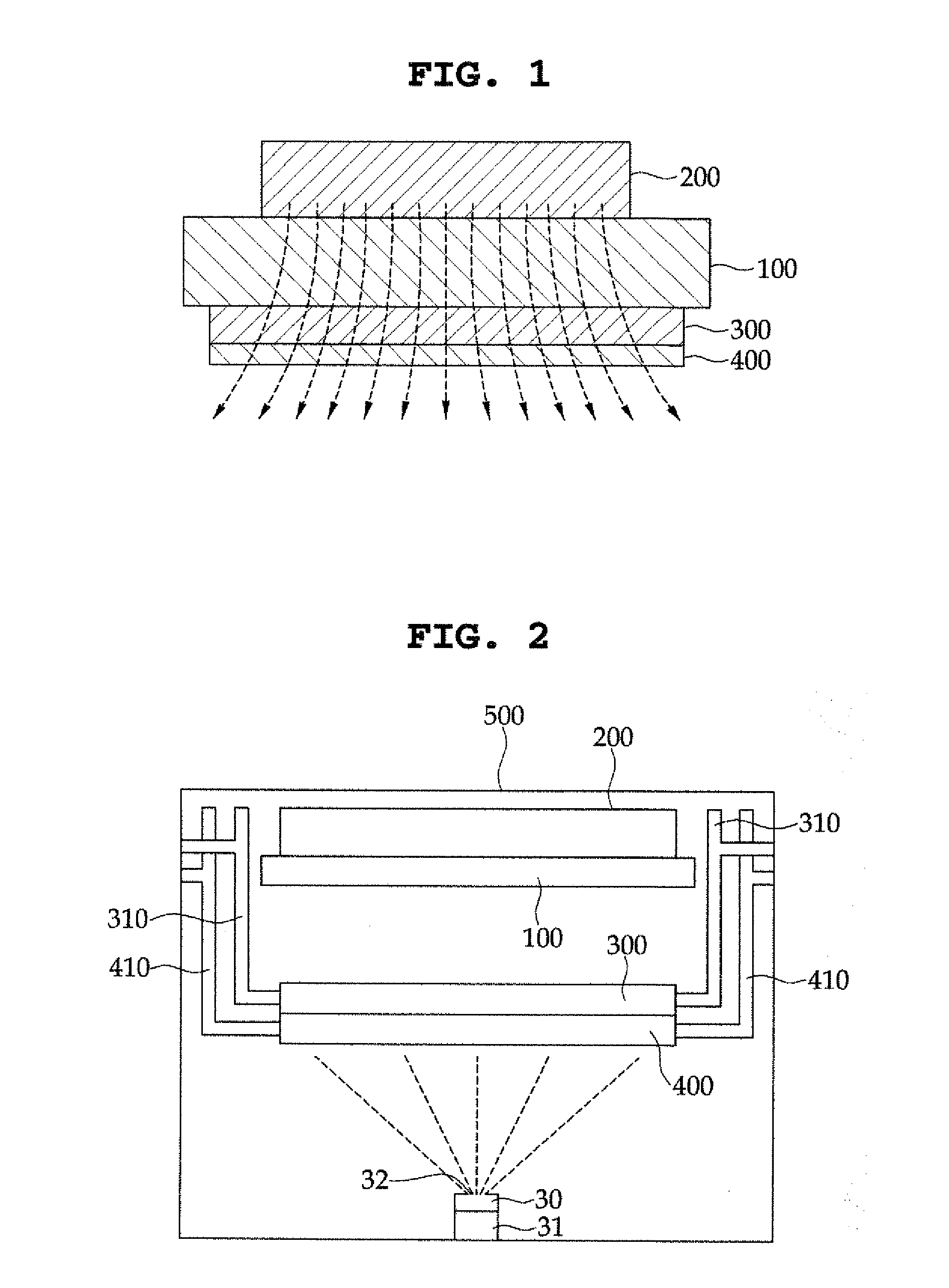
[0045]FIG. 1 is a schematic view illustrating a state where a substrate and a mask are fixed by a mask holding device.

[0046]In the structure of FIG. 1, at the upper side of a substrate holder 100, a magnetic means 200 such as a permanent magnet or an electromagnet is positioned, and at the lower side of the substrate holder 100, a substrate 300 and a mask 400 are held by using a magnetic force of the magnetic means 200.

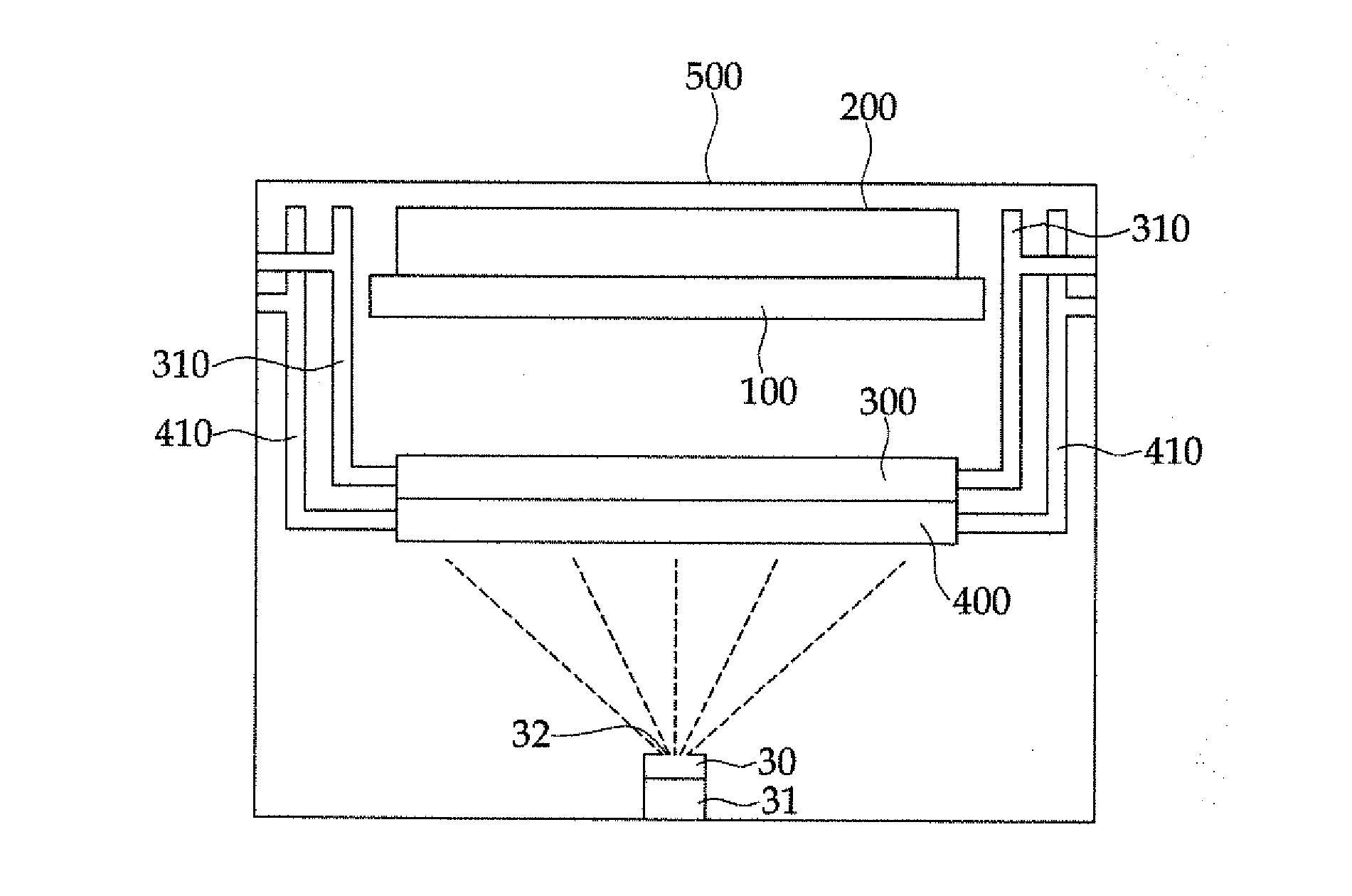
[0047]FIG. 2 is a view illustrating a deposition apparatus employing the above described mask holding device.

[0048]As shown in FIG. 2, in the deposition apparatus, within a chamber 500, the substrate holder 100, the magnetic means 200, the substrate 300, and the mask 400 are disposed. Also, at the bottom of the vacuum chamber 500, an evaporation source 30 including an evaporant 31 is disposed. At left and right sides of the substrate 300, substrate cla...


PUM

PropertyMeasurementUnit
weightaaaaaaaaaa
magnetic forceaaaaaaaaaa
polaritiesaaaaaaaaaa

Abstract

A mask holding device has a replaceable magnetic means, and a deposition apparatus for an organic light emitting device includes the mask holding device. The mask holding device is provided with magnets, and the magnets can be replaced as required so as to change the magnetic force of the mask holding device.

Description

CLAIM OF PRIORITY[0001]This application makes reference to, incorporates the same herein, and claims all benefits accruing under 35 U.S.C. §119 from an application earlier filed in the Korean Intellectual Property Office on the 14 Feb. 2011 and there duly assigned Serial No. 10-2011-0012873.BACKGROUND OF THE INVENTION[0002]1. Field of the Invention[0003]The present invention relates to a mask holding device having a replaceable magnetic means, and a deposition apparatus for an organic light emitting device including the same, in which the mask holding device is provided with magnets, and the magnets can be replaced as required so as to change the magnetic force of the mask holding device.[0004]2. Description of the Prior Art[0005]As semiconductor industries and electronic display industries have rapidly developed, flat panel displays (FPDs), such as a Liquid Crystal Display (LCD) Device, a Plasma Display Panel (PDP), an Electro Luminescent Display (ELD), a Vacuum Fluorescent Display...

Claims


Application Information

Patent Timeline
Patent Type & Authority Applications(United States)
IPC IPC(8): C23C16/04
CPCC23C14/12C23C14/042
Inventor KO, JUNG-WOO
Owner SAMSUNG DISPLAY CO LTD
Learn More