Stepping motor

a technology of stepping motors and stepping rods, which is applied in the direction of electrical equipment, dynamo-electric machines, supports/enclosements/casings, etc., can solve the problems of unclear whether or not the abovementioned effect can be obtained, and it is difficult to obtain a space for arranging the magnetic washer of the patent document 1. the effect of reducing the noise of stepping motor rotation and reducing the size of the secondary bearing

Active Publication Date: 2021-02-11
MINEBEAMITSUMI INC
View PDF0 Cites 1 Cited by
  • Summary
  • Abstract
  • Description
  • Claims
  • Application Information

AI Technical Summary

Benefits of technology

[0011]In the present invention, since magnetic permeability of the secondary bearing is set higher than that of the primary bearing, magnetic force (magnetic flux) of the rotor acts more strongly at the secondary bearing than at the primary bearing, and magnetic attractive force to the rotor is generated at the secondary bearing. Here, at the magnetic poles at the magnetized circumferential surface of the rotor, magnetic force acts over a range of about ½ of the pitch P of the magnetic poles along a depth direction from the outer circumferential surface. Therefore, in the present invention, since DB / 2 is not less than (DR / 2−P / 2), magnetic force of the magnetic poles of the rotor acts at the secondary bearing, and the rotor is attracted by the secondary bearing. In this way, striking noise occurring during rotation driving of the stepping motor can be reduced.
[0012]In the present invention, action and effect based on Formula 1 can be obtained only in a case in which the magnetic poles are arranged only on the outer circumferential surface of the rotor. However, in a case in which the magnetic poles are arranged on an end surface of the rotor, since greater magnetic force acts at the secondary bearing, the present invention does not exclude such an embodiment.
[0013]In the present invention, it is desirable that the secondary bearing include a small diameter portion and a large diameter portion, the small diameter portion be affixed to a covering member, and the large diameter portion face an end surface of the rotor. In this way, the size of the secondary bearing can be reduced, thereby reducing material cost, and the secondary bearing can be attached to the covering member via a step portion between the small diameter portion and the large diameter portion.
[0014]In the present invention, by arranging a resin washer between the rotor and the secondary bearing, metals of the rotor and the secondary bearing are prevented from making contact with each other, thereby avoiding the occurrence of abnormal noise.

Problems solved by technology

In such a case of a very small diameter motor, it is difficult to obtain a space to arrange the magnetic washer of the Patent Document 1.
Therefore, it is unclear whether or not the abovementioned effect can be obtained even in a case in which the bottom surface of the rotor magnet is not magnetized.

Method used


Image

  • Stepping motor
  • Stepping motor
  • Stepping motor

Examples


Embodiment Construction

Structure of Stepping Motor

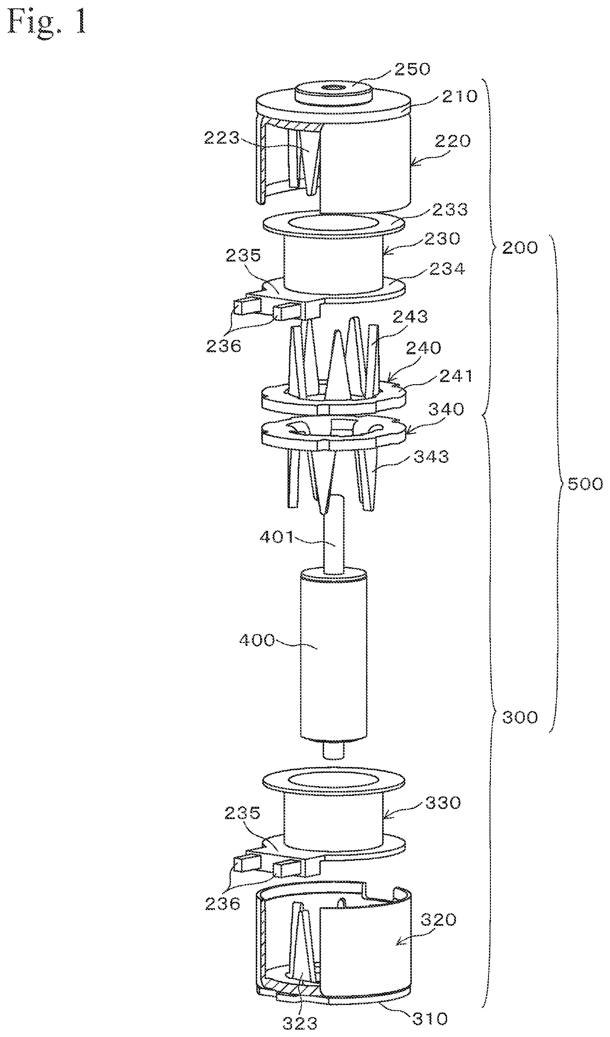
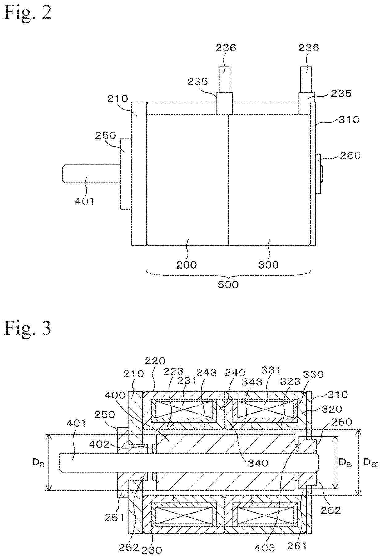
[0020]FIG. 1 shows a stepping motor 100 of the embodiment. The stepping motor 100 is a claw-pole-type two-phase PM-type (Permanent Magnet-type) stepping motor. The stepping motor 100 includes a stator 500. The stator 500 has a structure in which an A phase stator unit 200 and a B phase stator unit 300 are combined in an axial direction. Here, the A phase stator unit 200 and the B phase stator unit 300 have the same structure, and one is opposite to the other in an axial direction, back surfaces thereof are in contact and are combined, thereby constructing the stator 500.

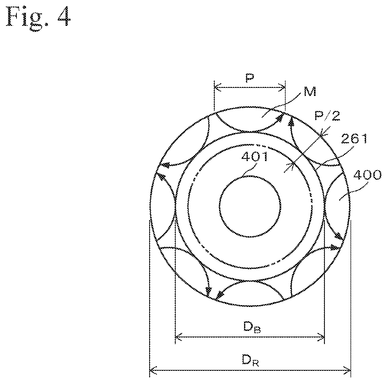
[0021]A front plate 210 is fixed to the A phase stator unit 200, and an end plate 310 is fixed to the B phase stator unit 300. The stator 500 has a substantially cylindrical shape, and a rotor 400 is contained therein in a rotatable condition.

[0022]The A phase stator unit 200 has a structure in which an outer yoke 220, a bobbin 230, and an inner yoke 240 are combined in an axial direction. ...


PUM


Abstract

A stepping motor has a relationship between an outer diameter of a rotor and an outer diameter of a bearing made of magnetic material that can be adjusted appropriately so as to impart magnetic attractive force to the bearing, the stepping motor including a rotor 400 made of a permanent magnet, a stator including multiple pole teeth 223, 243, 323 and 343 extending in an axial direction of the rotor 400 arranged at an outer circumferential side of the rotor 400, a bearing 250 rotatably supporting one end portion in the axial direction of the rotor 400, and a bearing 260 rotatably supporting the other end portion in the axial direction of the rotor 400. Magnetic permeability of the bearing 260 is greater than that of the bearing 250, the rotor 400 includes multiple magnetic poles on an outer circumferential surface along a circumferential direction of the rotor 400, and an outer diameter DR of the rotor 400, an outer diameter DB of a portion of the bearing 260 which is facing the rotor 400, and a pitch P of the multiple magnetic poles of the rotor 400 are set to satisfy the following relationship of formula 1
(DR−P)=<DB=<DR  (Formula 1).

Description

TECHNICAL FIELD[0001]The present invention relates to stepping motors, and in particular, relates to PM-type (Permanent Magnet-type) stepping motors having a rotor which is a permanent magnet and a stator having multiple pole teeth extending in an axial direction at an outer circumferential side of the rotor.BACKGROUND ART[0002]Conventionally, in the abovementioned PM-type stepping motor, a bearing rotatably supporting the rotor is installed, and there is a gap along the axial direction between the rotor and the bearing. For example, in a two-phase PM-type stepping motor, there is a phenomenon due to combination of excitation of two stators, in which the magnetic centers of the rotor and the stator are misaligned during driving of the stepping motor, and the rotor moves along an axial direction, thereby causing abnormal noise by collision with the bearing.[0003]To solve this phenomenon, a stepping motor is known in which a magnetic attractive force generating member attracting a rot...

Claims


Application Information

Patent Timeline
Patent Type & Authority Applications(United States)
IPC IPC(8): H02K37/14H02K7/08H02K37/24
CPCH02K37/14H02K2213/03H02K37/24H02K7/083H02K5/161H02K1/146H02K1/2706H02K1/2733H02K5/1675
Inventor SUEYOSHI, NOBUYUKIKINOSHITA, MITSUO
Owner MINEBEAMITSUMI INC
Why Eureka
Try Eureka