Electrodynamic multi-rotor helicopter

A multi-rotor and helicopter technology, applied in the field of general aircraft, to achieve the effect of low cost, light weight and low cost

Inactive Publication Date: 2015-05-06
王文有
View PDF6 Cites 11 Cited by
  • Summary
  • Abstract
  • Description
  • Claims
  • Application Information

AI Technical Summary

Problems solved by technology

[0003] In order to solve the above-mentioned problems existing in existing helicopters, the object of the present invention is to provide a kind of electric power multi-rotor helicopter

Method used


Image

  • Electrodynamic multi-rotor helicopter
  • Electrodynamic multi-rotor helicopter
  • Electrodynamic multi-rotor helicopter

Examples


Embodiment 1

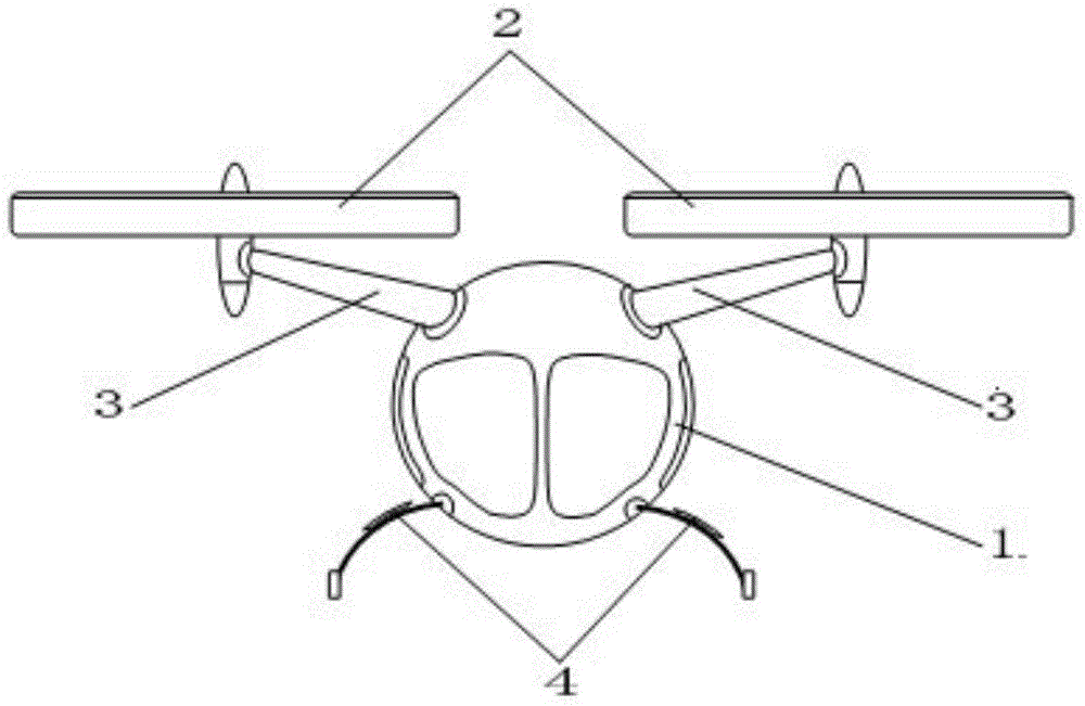
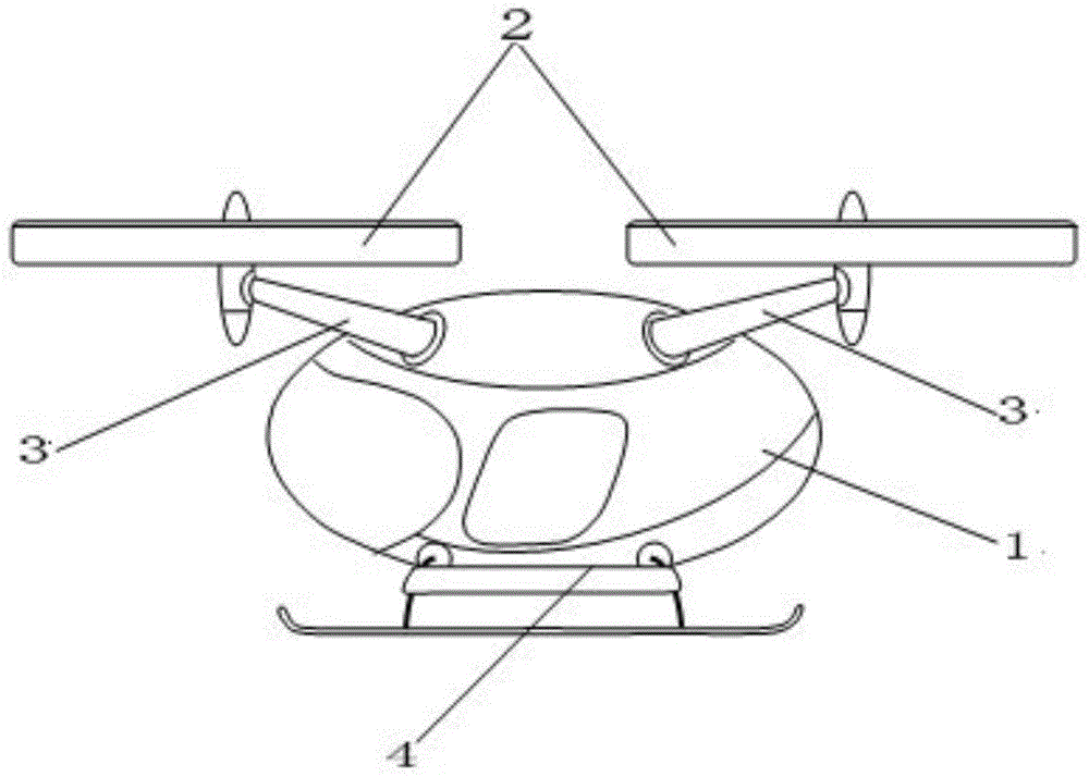
[0032] like Figure 1A , Figure 1B and Figure 1C As shown, the electric multi-rotor helicopter of this embodiment includes a fuselage 1, a powered rotor 2, a rotor support arm 3, a landing gear 4, a power supply system and a flight control system.

[0033] The fuselage 1 of this embodiment is streamlined as a whole, and the side projection and horizontal projection are elliptical. The fuselage 1 is provided with a cockpit, a load compartment and a battery compartment along the horizontal axis (ie, the direction of the long axis of the ellipse) in the forward direction. The battery compartment is arranged at the middle and rear part below the carrying compartment, the power supply system is placed in the battery compartment, and the flight control system is placed in the cockpit.

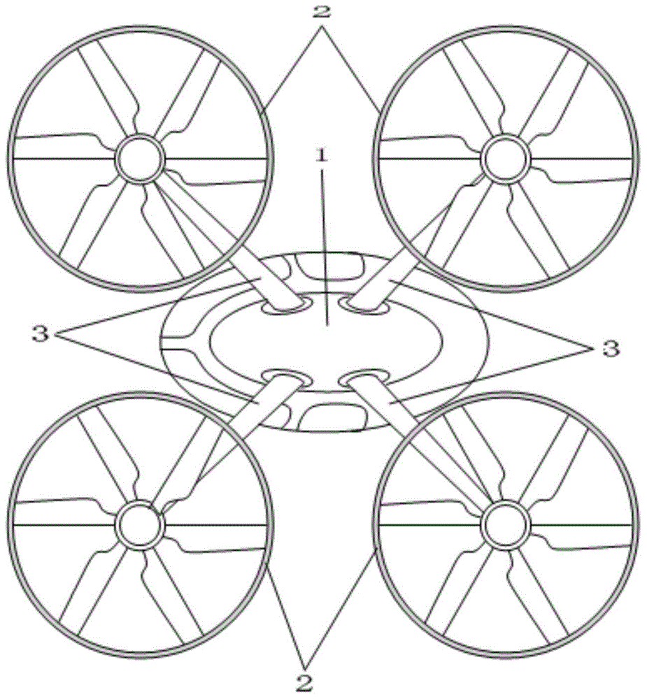
[0034] Four powered rotors 2 are evenly distributed along the circumferential direction above the fuselage 1, and there are two powered rotors 2 on the left and right sides of the horizontal axis ...

Embodiment 2

[0038] like Figure 2A , Figure 2B and Figure 2C As shown, the difference between the present embodiment and the first embodiment is that the fuselage 1 of the present embodiment is spherical, and the fuselage 1 is provided with a two-person cockpit, the bottom is provided with a battery compartment, and the power supply system is placed in the battery compartment. The flight control system is placed in the cockpit. Others are all the same as in Embodiment 1.

Embodiment 3

[0040] like Figure 3A , Figure 3B and Figure 3C As shown, the electric multi-rotor helicopter of this embodiment includes a fuselage 1, a powered rotor 2, a rotor support arm 3, a landing gear 4, a power supply system and a flight control system.

[0041] The fuselage 1 of this embodiment is streamlined as a whole, and the side projection and the horizontal projection are generally rectangular in length, and the fuselage 1 is provided with a cockpit, a load compartment and a battery along the horizontal axis (ie, the centerline of the length direction of the rectangle) in the forward direction. The battery compartment is located under the carrying compartment, the power supply system is placed in the battery compartment, and the flight control system is placed in the cockpit.

[0042] Six power rotors 2 are arranged on the top of the fuselage 1, and the power rotors 2 are symmetrically arranged on the left and right sides of the horizontal axis in the forward direction of...


PUM


Abstract

The invention belongs to the field of general aircrafts, and particularly relates to an electrodynamic multi-rotor helicopter. The electrodynamic multi-rotor helicopter comprises a fuselage, power rotors, a rotor support arm, a undercarriage, an electric supply system and a flight control system, wherein even power rotors are arranged above the fuselage, each power rotor is installed on the upper part of the fuselage through the rotor support arm, the undercarriage is arranged at the lower part of the fuselage, the electric supply system and the flight control system are respectively installed in a battery cabin and a cockpit in the fuselage; the structures of the power rotors are the same, and the power rotor comprises a screw propeller, a drive motor and fairings; the drive motor is installed on the fuselage through the rotor support arm, the screw propeller is connected with the output end of the drive motor, and fairings are respectively arranged at the lower end of the drive motor and the upper end of the drive motor above the screw propeller. The helicopter disclosed by the invention is compact in structure, flexible in movement, and large in lift-weight ratio, and has the advantages of being strong in adaptability, safe and reliable, economical, environment-friendly, simple in control, and low in maintenance charge.

Description

technical field [0001] The invention belongs to the field of general aircraft, in particular to an electric power multi-rotor helicopter. Background technique [0002] Helicopters with functions such as vertical take-off and landing and hovering in the air, especially those that can fly at low altitudes, have been more and more widely used in many fields. Up to now, the helicopter with this type of function has single-rotor helicopter, twin-rotor helicopter, and tilting-rotor helicopter models. However, due to the constraints of the power system and the transmission system structure, the constraints of the rotor variable pitch system mechanism and the paddle disk tilting system mechanism, and the constraints of the tail rotor or empennage device required to maintain balance, not only the noise is large, the manipulation is complicated, and the lift The weight ratio is low, the daily maintenance cost is high, there are also problems such as fuel pollution, and the large roto...

Claims


Application Information

Patent Timeline
Patent Type & Authority Applications(China)
IPC IPC(8): B64C27/08B64D27/24
CPCY02T50/60
Inventor 王文有
Owner 王文有
Why Eureka
Try Eureka