Elliptic-track treadmill with adjustable travel

a technology of adjustable travel and elliptical track, which is applied in the direction of electrical equipment, substation/switching arrangement details, gymnastic exercise, etc., can solve the problems of fixed inability to adjust, troublesome and inconvenient adjustment of elliptical track and travel of the pedals, etc., to achieve convenient adjustment of distance, smooth movement of the pedals, and convenient

Inactive Publication Date: 2006-11-09
CYCLING & HEALTH TECH IND R & D CENT
View PDF4 Cites 11 Cited by
  • Summary
  • Abstract
  • Description
  • Claims
  • Application Information

AI Technical Summary

Benefits of technology

[0010] The crank, adjustment member and link of the linking mechanism and the upright stem of the bed form a four-link mechanism so that the power can be truly transmitted to the slide bars of the pedals to smoothly move the pedals in an elliptic track. In addition, the free end of the adjustment member can be axially telescopically moved to adjust the distance between the pedals. In exercise, a user can readily adjust the distance according to the user's own step distance. Therefore, the adjustment can be conveniently performed.
[0011] It is a further object of the present invention to provide the above elliptic-track treadmill in which the crank via the adjustment member is connected with the slide bar of the pedal, whereby the adjustment member can adjust the elliptic track and travel of the pedals. Accordingly, the elliptic track and travel of the pedals can be adjusted without changing the length of the crank. Therefore, the crank can drive the slide bar to rotate without applying great force thereon.

Problems solved by technology

In a conventional elliptic track-treadmill, the track and travel of the pedals is fixed and cannot be adjusted in accordance with the height and configuration of different users.
This often leads to inconvenience to a user in exercise.
Therefore, it is quite troublesome and inconvenient to adjust the elliptic track and travel of the pedals 82.
It is hard for the crank to drive the slide bar to rotate, especially after the crank is extended and the distance between the crank and the rotary shaft is elongated.

Method used


Image

  • Elliptic-track treadmill with adjustable travel
  • Elliptic-track treadmill with adjustable travel
  • Elliptic-track treadmill with adjustable travel

Examples


Embodiment Construction

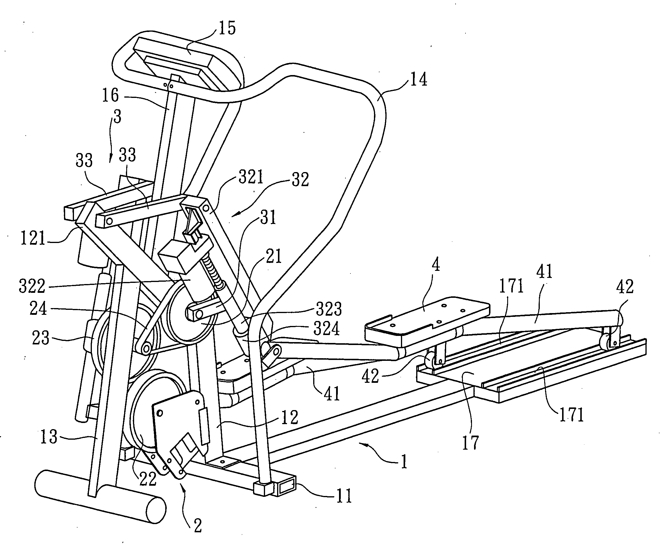
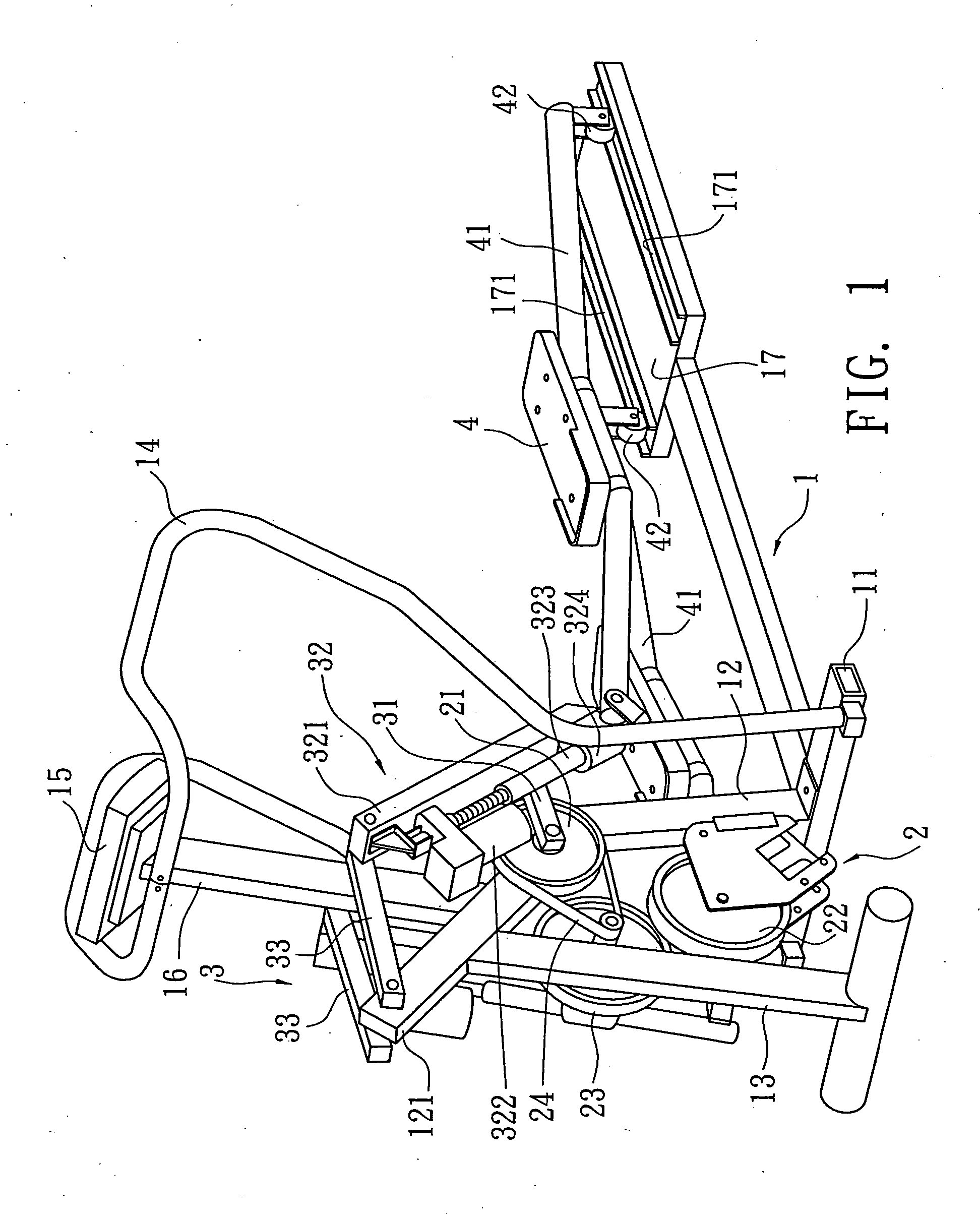
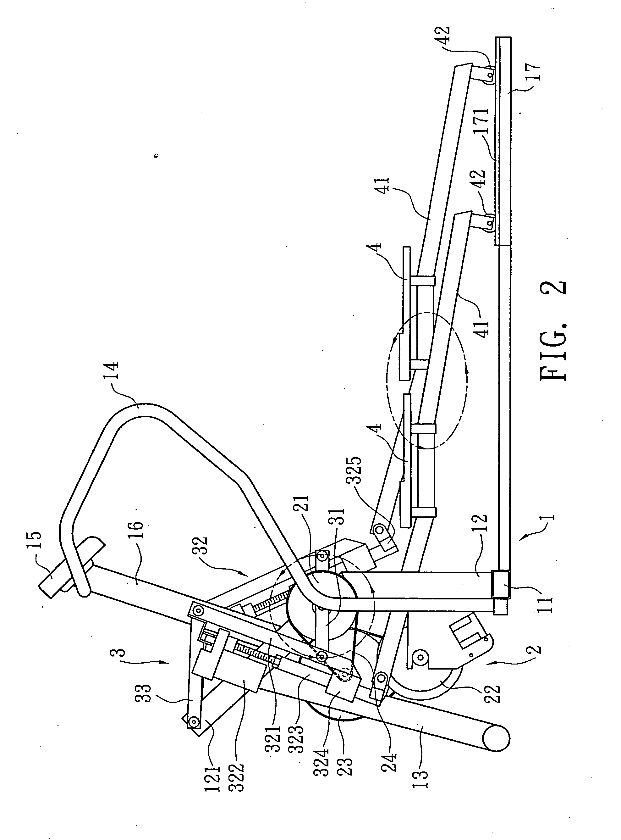
[0021] Please refer to FIGS. 1 and 2. The elliptic-track treadmill with adjustable travel of the present invention includes a bed 1 placed on the ground, a transmission unit 2 mounted in the bed 1 and a linking mechanism 3 driven by the transmission unit 2. The linking mechanism 3 serves to drive two pedals 4 to move in elliptic track.

[0022] The bed 1 has a transverse beam 11 at front end for supporting the front end of the bed 1 on the ground. An upright stem 12 upward extends from middle section of the transverse beam 11. The upright stem 12 has an upper extending section 121 which is forward inclined. A front bar 13 downward extends from the bottom of the extending section 121 to help in supporting the front end of the bed 1 on the ground. Two rails 14 respectively upward extend from two ends of the transverse beam 11 of the bed 1. A panel 15 is disposed between the rails 14. A supporting bar 16 is fixedly connected between the bottom of the panel 15 and the extending section 12...


PUM


Abstract

An elliptic-track treadmill with adjustable travel, including: a bed placed on the ground, an upright stem upward extending from one end of the bed; a transmission unit mounted on the upright stem; and a linking mechanism drivable by the transmission unit to drive two pedals to move in an elliptic track. The linking mechanism includes a pair of cranks drivable by the transmission unit. One end of each crank is pivotally connected with one end of an adjustment member. The adjustment member has an axially telescopic free end pivotally connected with the crank. The free end is connected with the pedal. The other end of the adjustment member is pivotally connected with one end of a link. The other end of the link is pivotally connected with each side of top end of the upright stem of the bed.

Description

BACKGROUND OF THE INVENTION [0001] The present invention is related to an elliptic-track treadmill with adjustable travel, and more particularly to an elliptic-track treadmill which transmits power by means of a four-like mechanism. In addition, the elliptic track and travel of the pedals of the elliptic-track treadmill are adjustable. [0002] In a conventional elliptic track-treadmill, the track and travel of the pedals is fixed and cannot be adjusted in accordance with the height and configuration of different users. This often leads to inconvenience to a user in exercise. [0003]FIG. 7 shows an elliptic-track treadmill in which the elliptic track and travel of the pedals are adjustable. The elliptic-track treadmill includes a bed 6 rested on the ground, an upright stem 61 disposed at front end of the bed 6 and a transmission unit 7 disposed at rear end of the bed 6. The transmission unit 7 has a transmission wheel 71 and two links 72 respectively pivotally connected with two sides ...

Claims


Application Information

Patent Timeline
Patent Type & Authority Applications(United States)
IPC IPC(8): H02B1/00A63B22/00A63B22/04A63B23/04
CPCA63B21/225A63B22/0015A63B2022/0676A63B22/203A63B22/0664
Inventor LUI, PAO-PAOWU, HUNG SHENGCHEN, CHIU-CHIEH
Owner CYCLING & HEALTH TECH IND R & D CENT
Why Eureka
Try Eureka