Illuminating apparatus

a technology of illumination apparatus and fan, which is applied in the direction of lighting protection devices, medical lighting, lighting heating/cooling arrangements, etc., can solve the problems of fan b>30/b> producing vibrations that the user finds disturbing

Inactive Publication Date: 2006-11-09
HEINE OPTOTECHN
View PDF19 Cites 15 Cited by
  • Summary
  • Abstract
  • Description
  • Claims
  • Application Information

AI Technical Summary

Benefits of technology

[0006] It is the object of the invention to provide with the aid of means of simple design a compact and light illuminating apparatus that is agreeable to wear for the user.

Problems solved by technology

It is known for the purpose of dissipating the heat to use relatively large heat sinks that are heavy and voluminous and this is disagreeable, in particular, when using headworn instruments and lighting devices.
However, it has been shown in practice that the fan 30 produces vibrations that the user finds disturbing when working.

Method used


Image

  • Illuminating apparatus
  • Illuminating apparatus
  • Illuminating apparatus

Examples


Embodiment Construction

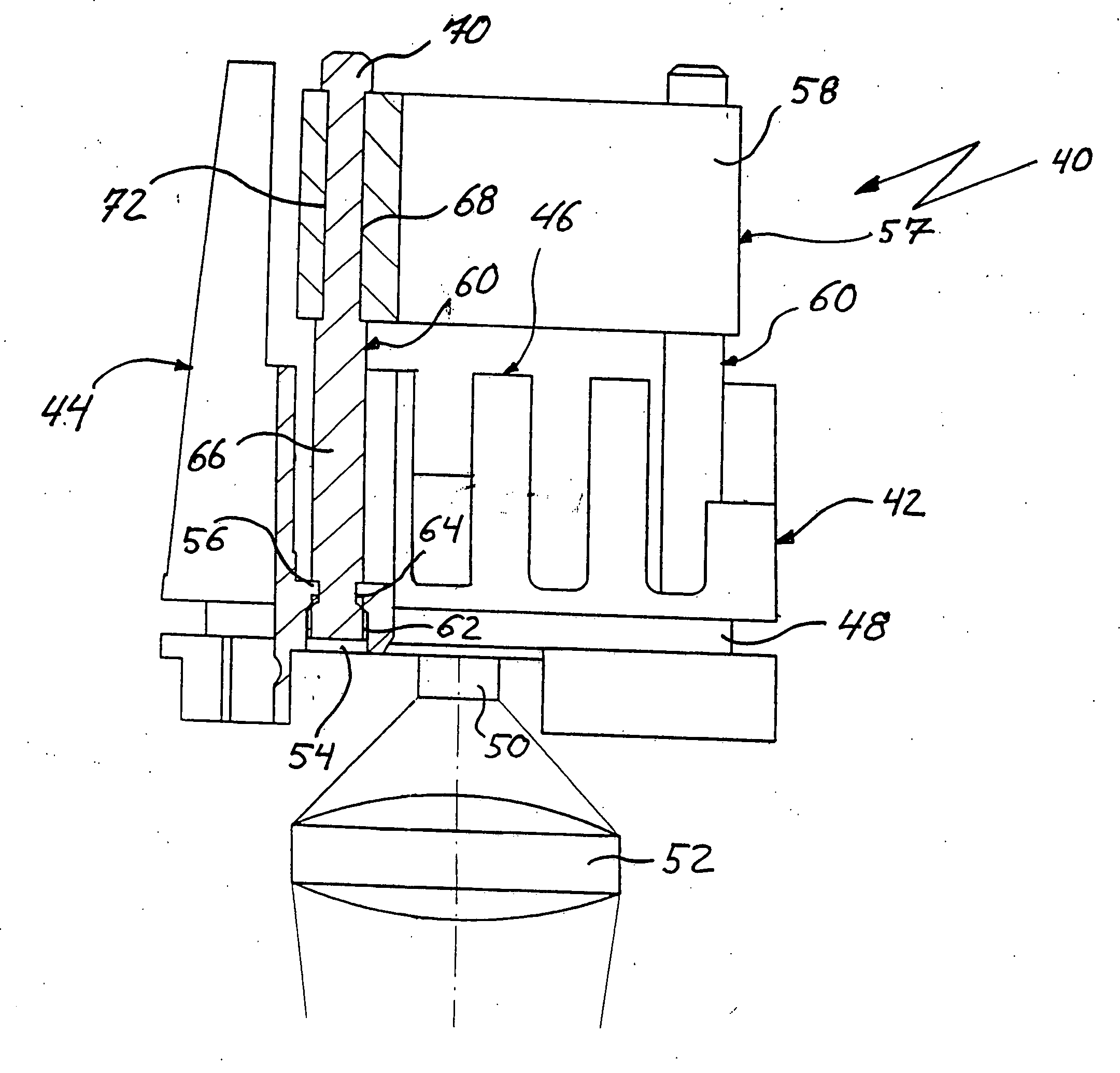
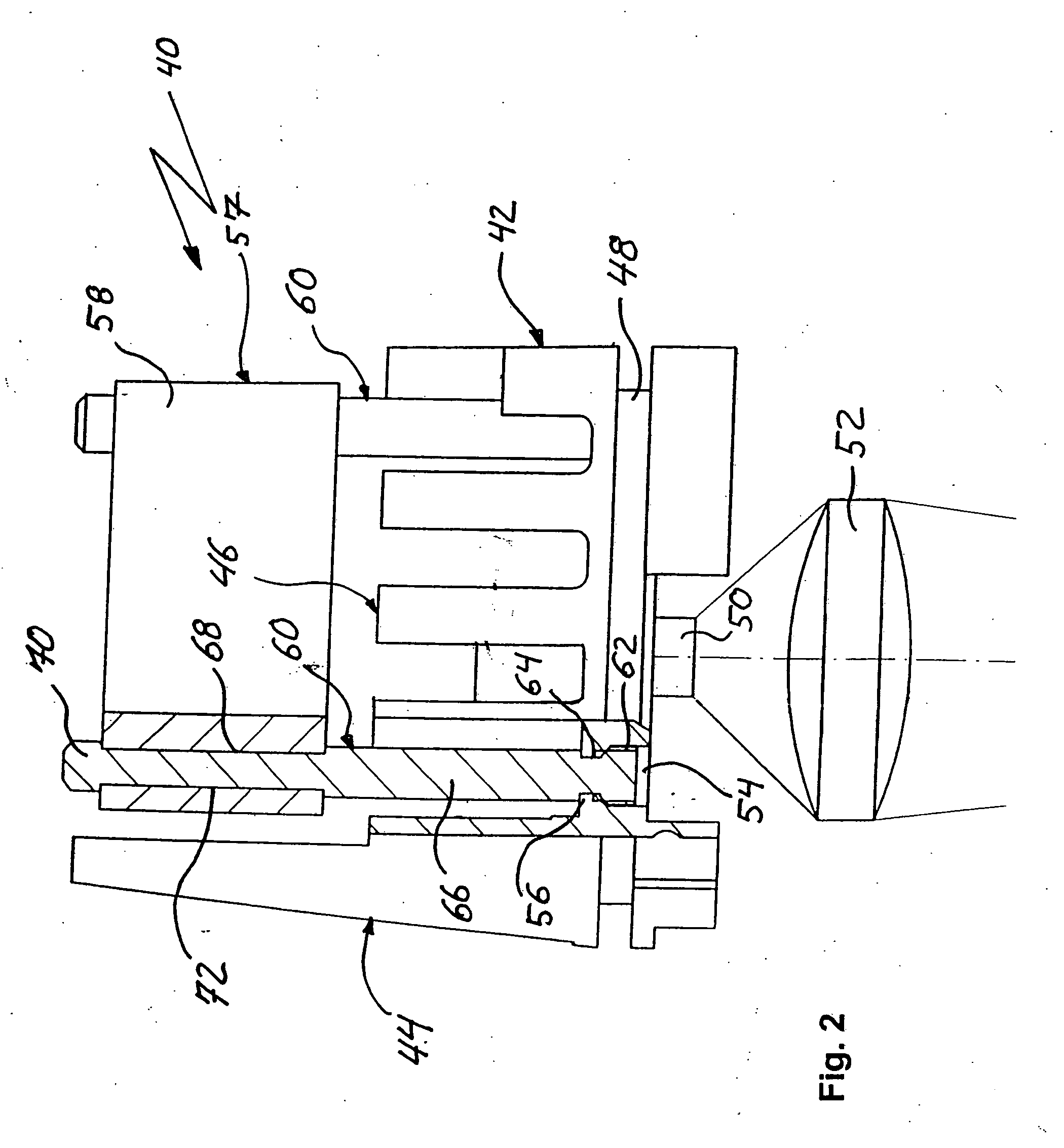
[0015] The illuminating apparatus 40 according to the invention comprises a heat sink 42 made from aluminum that is bounded below by a base 48. Extending upward from the base 48 at the front, that is to say on the left-hand side in FIG. 2, is a row of long cooling webs 44 of which only one is to be seen because of the side view. On each of both sides of the heat sink 42 a respective row of lateral cooling webs 46 is arranged with spacing to each other, the height of the lateral cooling webs corresponding approximately to half the height of the front cooling webs 44. An LED 50 is mounted centrally on the underside of the base 48. A positive lens 52 is arranged in the illuminating path below the LED 50.

[0016] For the purpose of active ventilation of the heat sink 42, a fan 57 with an impeller is arranged above the end faces of the cooling webs 46 and essentially comprises a cuboid housing 58, the housing 58 being situated deeper than the upper end face of the cooling webs 44.

[0017] ...


PUM


Abstract

An illuminating apparatus for handheld or headworn instruments comprises a luminous means (50), a heat sink (42) for dissipating heat produced by the luminous means (50), and a ventilation device (57), fitted on the heat sink (42), for feeding cooling air to the heat sink (42). A damping device (60) for damping the oscillations generated by the ventilation device (57) is provided between the heat sink (42) and the ventilation device (57).

Description

BACKGROUND OF THE INVENTION [0001] 1. Field of the Invention [0002] The invention relates to an illuminating apparatus for handheld or headworn a luminous means, comprising a heat sink for dissipating heat produced by the luminous means, and a ventilation device, mounted on the heat sink, for feeding cooling air to the heat sink. [0003] 2. Description of the Background Art [0004] Such illuminating apparatuses are used inter alia with headlamps, ophthalmoscopes and luminous means for binocular magnifiers. Arranged in these illuminating apparatuses as luminous means is, for example, a light-emitting diode with a power of 3 W, or a halogen lamp that generates through power loss a large quantity of heat that must be dissipated in order to prevent damage to the luminous means and the electronics associated therewith, as well as to prevent excessive heating of the housing. It is known for the purpose of dissipating the heat to use relatively large heat sinks that are heavy and voluminous ...

Claims


Application Information

Patent Timeline
Patent Type & Authority Applications(United States)
IPC IPC(8): H05K7/20F21V15/01F21V15/04F21V29/02
CPCA61B1/0684A61B3/0008F21L14/02F21Y2101/02F21V29/40F21W2131/20F21V21/084F21V29/67F21V29/70F21Y2115/10F21V15/04
Inventor HEINE, HELMUTHEINE, OLIVERDUY, SEBASTIANSCHLOESSER, HARTMUTSCHADE, DIRK
Owner HEINE OPTOTECHN
Why Eureka
Try Eureka