Detection of intervertebral disk orientation in spine images using curve evolution

Inactive Publication Date: 2006-11-09
SIEMENS MEDICAL SOLUTIONS USA INC
View PDF4 Cites 17 Cited by
  • Summary
  • Abstract
  • Description
  • Claims
  • Application Information

AI Technical Summary

Problems solved by technology

Transverse imaging planning is done manually and is time-c

Method used


Image

  • Detection of intervertebral disk orientation in spine images using curve evolution
  • Detection of intervertebral disk orientation in spine images using curve evolution
  • Detection of intervertebral disk orientation in spine images using curve evolution

Examples


Embodiment Construction

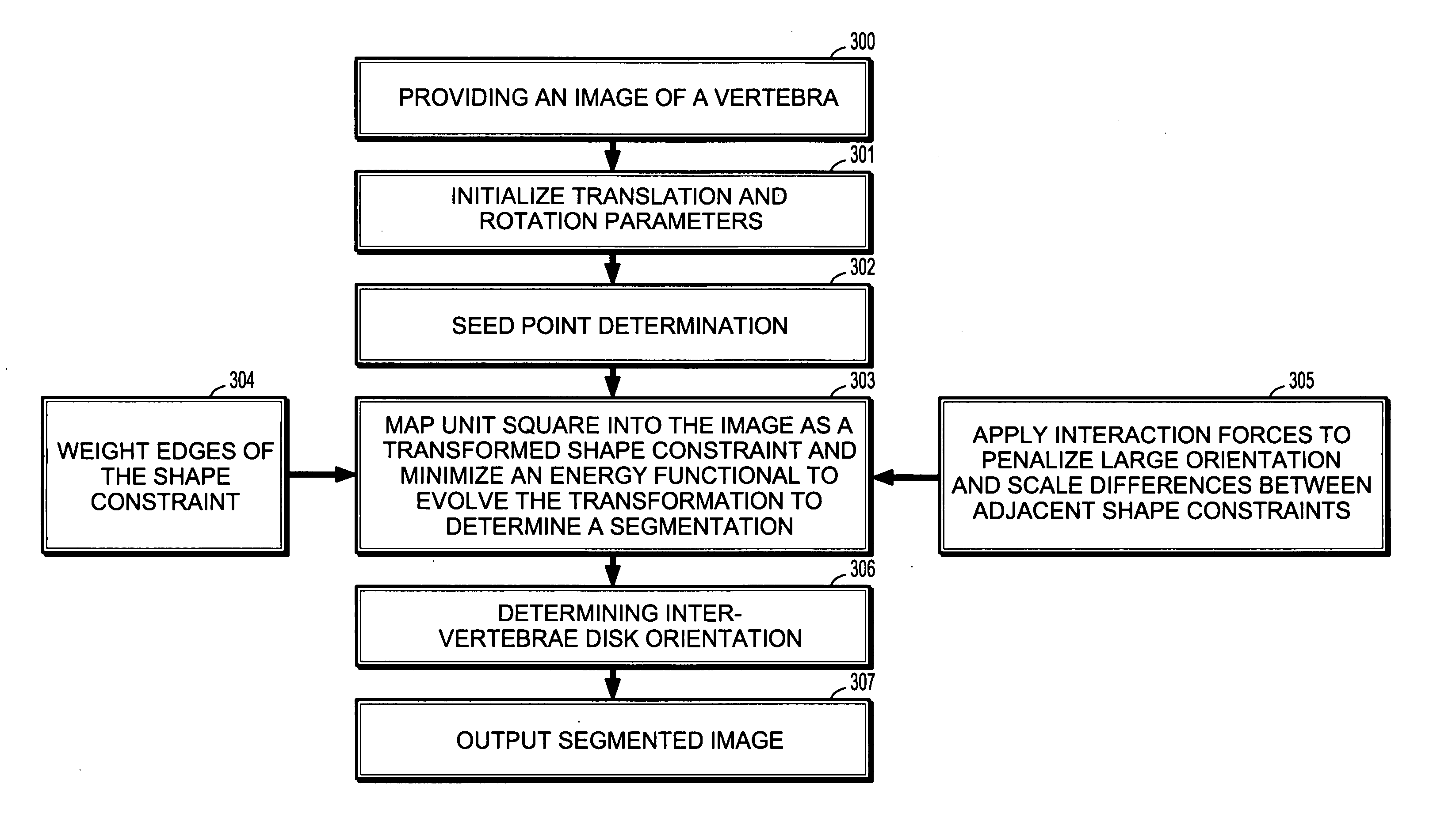
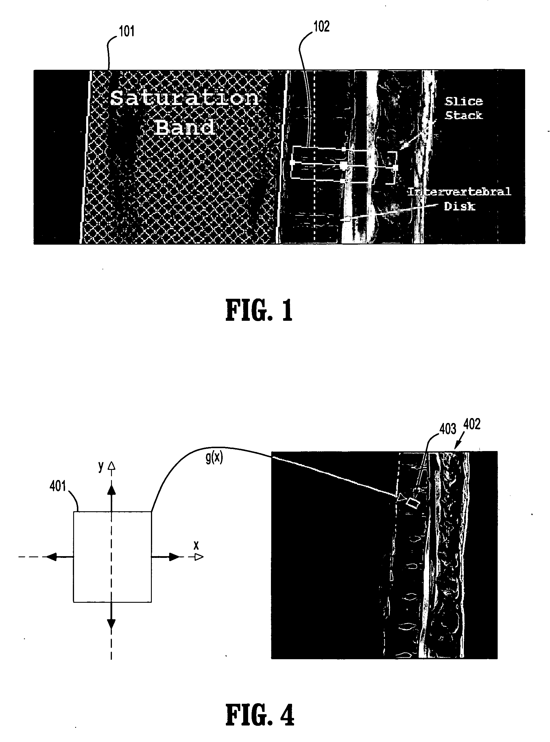
[0021] According to an embodiment of the present disclosure, a method for determining inter-vertebral disk orientation in a magnetic resonance (MR) image of a spine implements an active contour theory and enforces a shape constraint to avoid leaks through weak or non-existent boundaries. The method represents a vertebra as a rectangle, modeled as a transformation applied to the unit square. The method may be implemented for setting up transverse image acquisition for diagnosis of inter-vertebral disk pathologies.

[0022] A regional flow integrated along the rectangle's perimeter updates the rectangle's transformation to achieve the segmentation. Further constraints are added so that adjacent rectangles have similar orientation and scale. The inter-vertebral disk orientation is inferred by finding the bounding edges of adjacent vertebrae. Since each vertebra can be geometrically approximated by a rectangle, this a priori shape constraint is incorporated to increase robustness.

[0023] ...


PUM


Abstract

A computer-implemented method for vertebrae segmentation includes providing an image of a plurality of vertebrae, and determining a seed in each of at least two adjacent vertebrae in the image. The method further includes mapping a unit square to the seeds in the image as corresponding shape constraints on a segmentation, evolving the shape constraints to determine the segmentation of the adjacent vertebrae, wherein evolutions of the shape constraints interact, and outputting a segmented image indicating a location of the vertebra.

Description

[0001] This application claims priority to U.S. Provisional Application Ser. No. 60 / 664,418, filed on Mar. 23, 2005, which is herein incorporated by reference in its entirety.BACKGROUND OF THE INVENTION [0002] 1. Technical Field [0003] The present invention relates to image processing, and more particularly to a system and method for vertebrae segmentation including a determination of disk orientation. [0004] 2. Discussion of Related Art [0005] Magnetic resonance (MR) spine imaging has been widely used for non-invasive detection of different abnormalities and diseases in the spinal column, vertebrae, and inter-vertebral disks. In typical MR spine imaging cases, a patient is initially scanned to obtain a set of T2-weighted sagittal images or coronal localizer images. If an abnormality of an inter-vertebral disk is found, a transverse scan is performed. The orientation of the transverse images is planned parallel to the major axis of the disk and the center of the transverse images is...

Claims


Application Information

Patent Timeline
IPC IPC(8): G06K9/00G06K9/34
CPCG06T7/0083G06T7/0089G06T2207/30012G06T2207/20104G06T2207/20156G06T2207/10088G06T7/149G06T7/12
Inventor ABUFADEL, AMERSLABAUGH, GREGORY G.ODRY, BENJAMINZHANG, LIUNAL, GOZDE
Owner SIEMENS MEDICAL SOLUTIONS USA INC
Why Eureka
Try Eureka