Ambient air clothes dryer

a clothes dryer and ambient air technology, applied in the direction of drying machines, drying chambers/containers, light and heating apparatus, etc., can solve the problems of increasing the cost of operation of such conventional dryers, undesirable heat generation, and not particularly undesirable residual heat output into the structure, so as to save weight, complexity, and energy

Inactive Publication Date: 2006-11-16
FORD LARRY W
View PDF13 Cites 6 Cited by
  • Summary
  • Abstract
  • Description
  • Claims
  • Application Information

AI Technical Summary

Benefits of technology

[0008] The ambient air clothes dryer is an automated device including a motor-powered rotating drum having a fan providing axial airflow through the drum. No dedicated heating element is provided. Some embodiments include a fan motor and an additional motor to rotate the drum, while other embodiments utilize a belt or other drive from the fan output shaft to drive a jackshaft to rotate the drum, thereby saving weight, complexity, and energy. Yet another embodiment may be devoid of any fan or air circulation device, and may include only a motor to rotate the drum. This embodiment includes means for the removable and temporary installation of a conventional “box fan” therewith, to provide the air circulation required. Any or all of the embodiments may include a timer and / or humidity detector to provide for automatic shutoff of the fan and drum when the laundry is dry and / or a predetermined time has been reached.
[0009] The portability of the device allows it to be used indoors or outdoors, as desired. The device may take advantage of ambient heating sources within the home or other structure if so desired, e.g., a heat register, radiator, Franklin stove, etc., to provide some heating of the air, which then passes through the dryer drum. This also provides the beneficial effect of humidifying the air within the structure in colder weather. The device may be constructed to utilize twelve-volt power, if so desired, for use in camping when an automotive electrical system is available.

Problems solved by technology

Still, the residual heat output into the structure was not considered to be particularly undesirable, even in warmer conditions, as the energy costs required to operate air conditioning systems were much lower in the past.
However, with ever-increasing energy costs, the cost of operation of such conventional dryers has climbed considerably over the years, and even more so when the energy required to dissipate their heat output is considered.
While conventional hot air clothes dryers have their place in very damp and / or cool climates, the heat they develop is an undesirable side effect of the drying operation in many parts of the country during much of the year.
The alternative of the conventional clothes line is not suitable for many households due to the frequency of damp weather in many areas and seasons, and the time and labor required to tediously pin up each garment or article to the line and remove them, perhaps several hours later, when they are dry.
While some clothes dryers have been developed in the past that do not provide a source of heat during the drying operation, such dryers have not been found entirely satisfactory.

Method used


Image

  • Ambient air clothes dryer
  • Ambient air clothes dryer
  • Ambient air clothes dryer

Examples


first embodiment

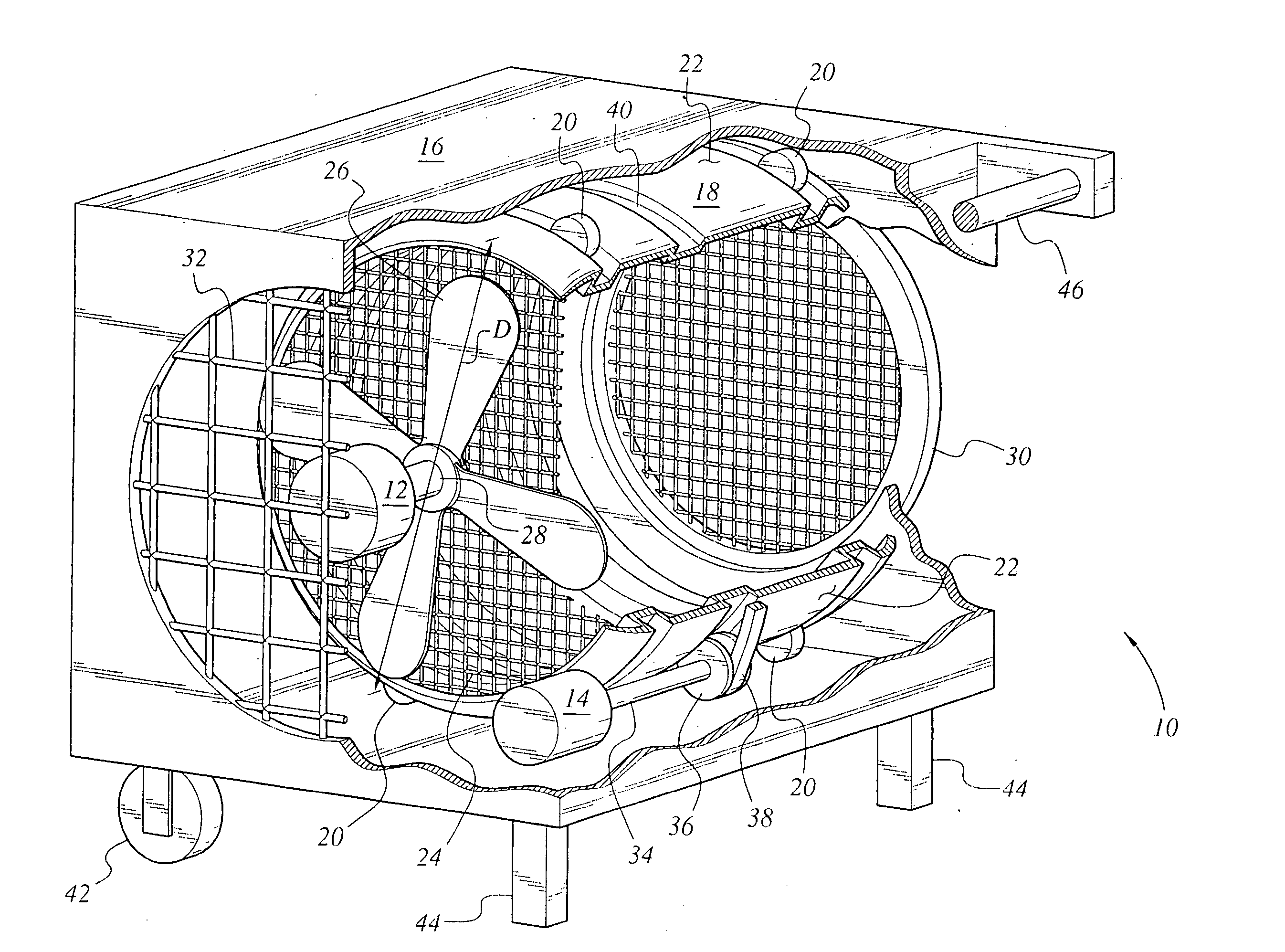
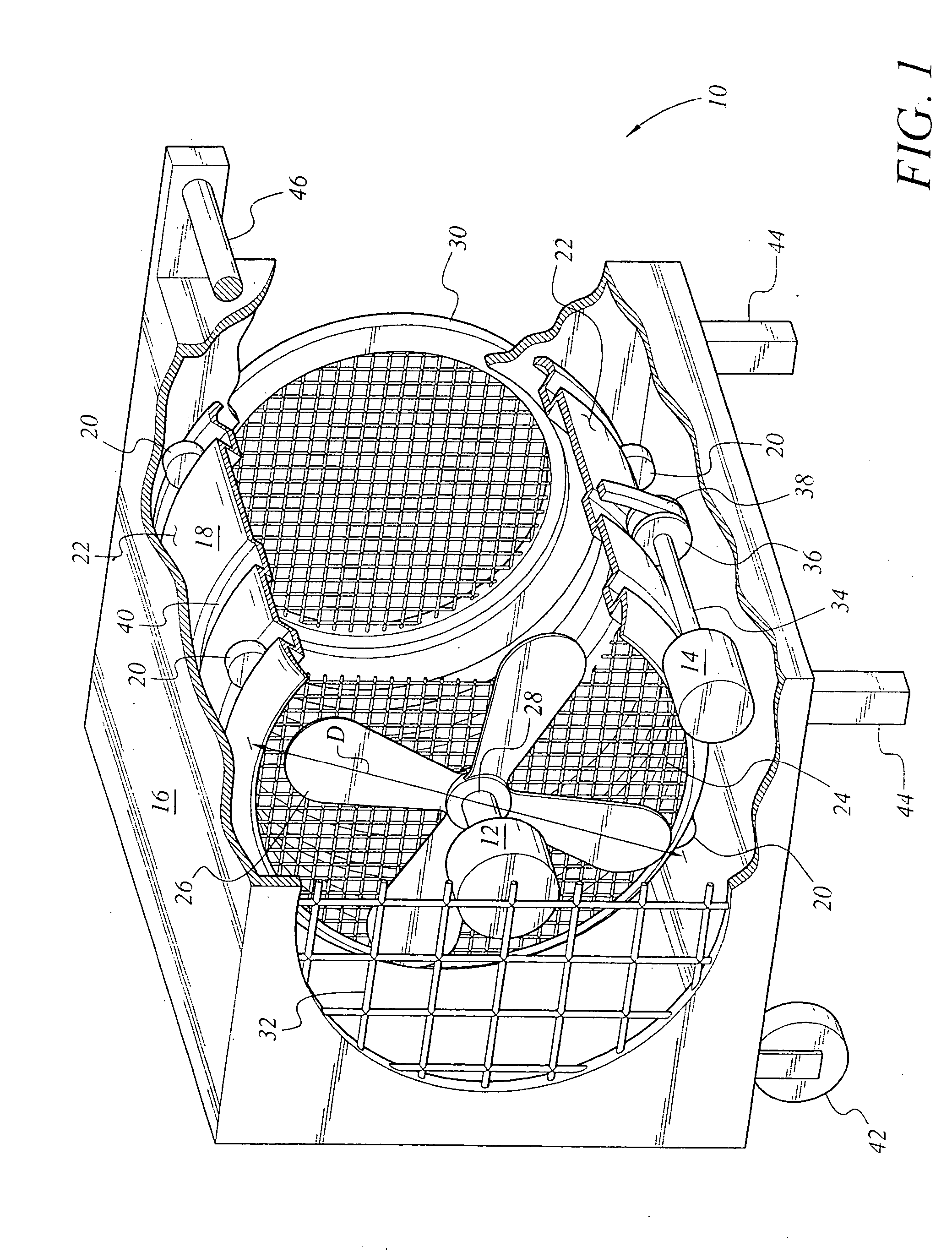
[0018]FIG. 1 of the drawings illustrates the present dryer 10, in which a separate fan motor 12 and drum rotation motor 14 are employed. The dryer 10 includes a housing or shell 16 having a hollow dryer drum 18 therein. The drum 18 rotates within the housing 16, and is supported by drum support wheels 20 or other mechanism installed internally within the housing 16. The dryer drum 18 has an impervious, generally cylindrical wall 22 having a diameter D. A screened airflow inlet end 24 is positioned adjacent the fan motor 12 with its fan 26 and fan drive shaft 28, with a screened airflow outlet end door 30 located opposite the inlet end 24 of the drum 18. The two screened ends 24 and 30 are preferably of a sufficiently fine mesh or gauge as to preclude the passage of small articles (e.g., loose change, buttons, etc.) therethrough, and have diameters closely approaching the diameter D of the dryer drum 18. The screen of the outlet door 30 may have a mesh or gauge sufficiently fine to s...

embodiment 10

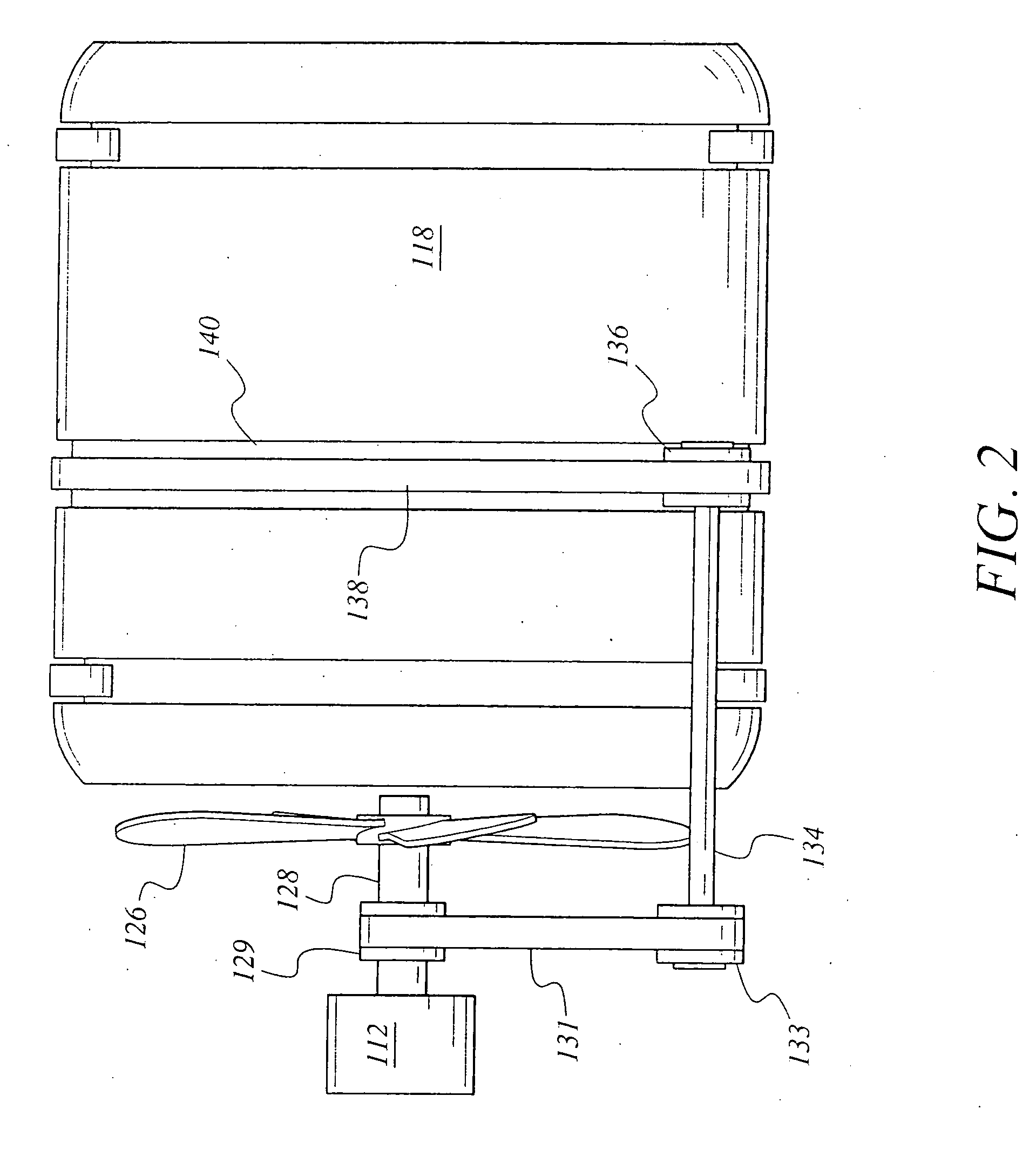
[0022]FIG. 2 provides a side elevation view of an alternative drum drive system, in which the fan drive is also used to rotate the drum. In FIG. 2, the fan motor 112 drives an output shaft 128 to which the fan 126 is connected, as in the corresponding components 12, 28, and 26 of the embodiment 10 of FIG. 1. However, the fan motor output shaft 128 may include a drive belt pulley 129 thereon, with a jackshaft drive belt 131 extending from the fan motor shaft pulley 129 to a driven pulley 133 on a radially offset jackshaft or drum drive shaft 134. The shaft 134 includes a drum drive belt pulley 136 at its distal end, with a drum drive belt 138 extending around the pulley 136 and riding in a circumferential groove 140 around the dryer drum 118. It will be seen that the dryer drum 118 and drum drive belt 138 may be identical to the corresponding components 18 and 38 illustrated in FIG. 1 and described further above. The distinction between the configuration of FIG. 1 and that of FIG. 2 ...


PUM


Abstract

The ambient air clothes dryer is an automated device providing axial flow of unheated ambient air through the dryer drum. The dryer may include different drum drive systems, timer and / or humidity detector controls, and a configuration utilizing a separate, portable fan for temporary, removable installation with the dryer housing to provide airflow through the drum. The ambient air dryer greatly reduces energy requirements for drying laundry when compared to conventional heated air dryers, and is quite effective in warm and / or dry climates. The ambient air dryer is portable and may be used indoors or outdoors. The device may be configured to use twelve-volt power from a motor vehicle for use in camping. When used indoors, the device may be placed with a heat source (heat register, etc.) to draw warm air through the drum while humidifying the air as it passes through damp laundry in the drum.

Description

REFERENCE TO RELATED PATENT APPLICATION [0001] This application claims the benefit of U.S. Provisional Patent Application Ser. No. 60 / 630,165, filed on Nov. 22, 2004.BACKGROUND OF THE INVENTION [0002] 1. Field of the Invention [0003] The present invention relates to automated devices for drying clothing and laundry. More specifically, the ambient air clothes dryer is a clothes dryer devoid of any dedicated heating elements or systems for heating the air. [0004] 2. Description of the Related Art [0005] The development of the automatic clothes dryer has been a great labor saving device for most households and, along with the automatic washing machine, has served to facilitate the commercial laundry industry as well. Automatic clothes dryers were initially developed when energy costs were relatively low, and accordingly make use of gas or electrical heat to accelerate the drying process. As a byproduct of the heat developed, the home or other structure is also heated, even though most ...

Claims


Application Information

Patent Timeline
Patent Type & Authority Applications(United States)
IPC IPC(8): F26B11/02D06F34/08
CPCD06F58/02D06F2103/44D06F2103/34D06F34/08
Inventor FORD, LARRY W.
Owner FORD LARRY W
Why Eureka
Try Eureka