Air conditioner

a technology for air conditioners and air conditioners, applied in the direction of lighting and heating apparatus, machine operation modes, heating types, etc., can solve the problems of not being able to achieve the temperature control other than temperature control, and the inability of plural indoor units to individually hold to the optimal temperature and humidity condition

Inactive Publication Date: 2006-11-16
MITSUBISHI ELECTRIC CORP
View PDF4 Cites 90 Cited by
  • Summary
  • Abstract
  • Description
  • Claims
  • Application Information

AI Technical Summary

Benefits of technology

[0005] The invention has been conducted in order to solve the above-discussed problems. It is an object of the invention to provide an air conditioning apparatus in which an outdoor unit is connected to plural indoor units, and each of the indoor units can perform a temperature control such as a cooling operation or a heating operation, and a humidity control such as a humidifying operation and a dehumidifying operation.

Problems solved by technology

However, the air conditioning apparatuses of JP-A-5-99525 and JP-A-2000-105014 have a problem in that a humidity control other than a temperature control cannot be performed.
The air conditioning apparatus disclosed in JP-A-2002-89988 has a problem in that plural indoor units cannot be individually held to an optimum temperature and humidity condition.

Method used


Image

  • Air conditioner
  • Air conditioner
  • Air conditioner

Examples


embodiment 1

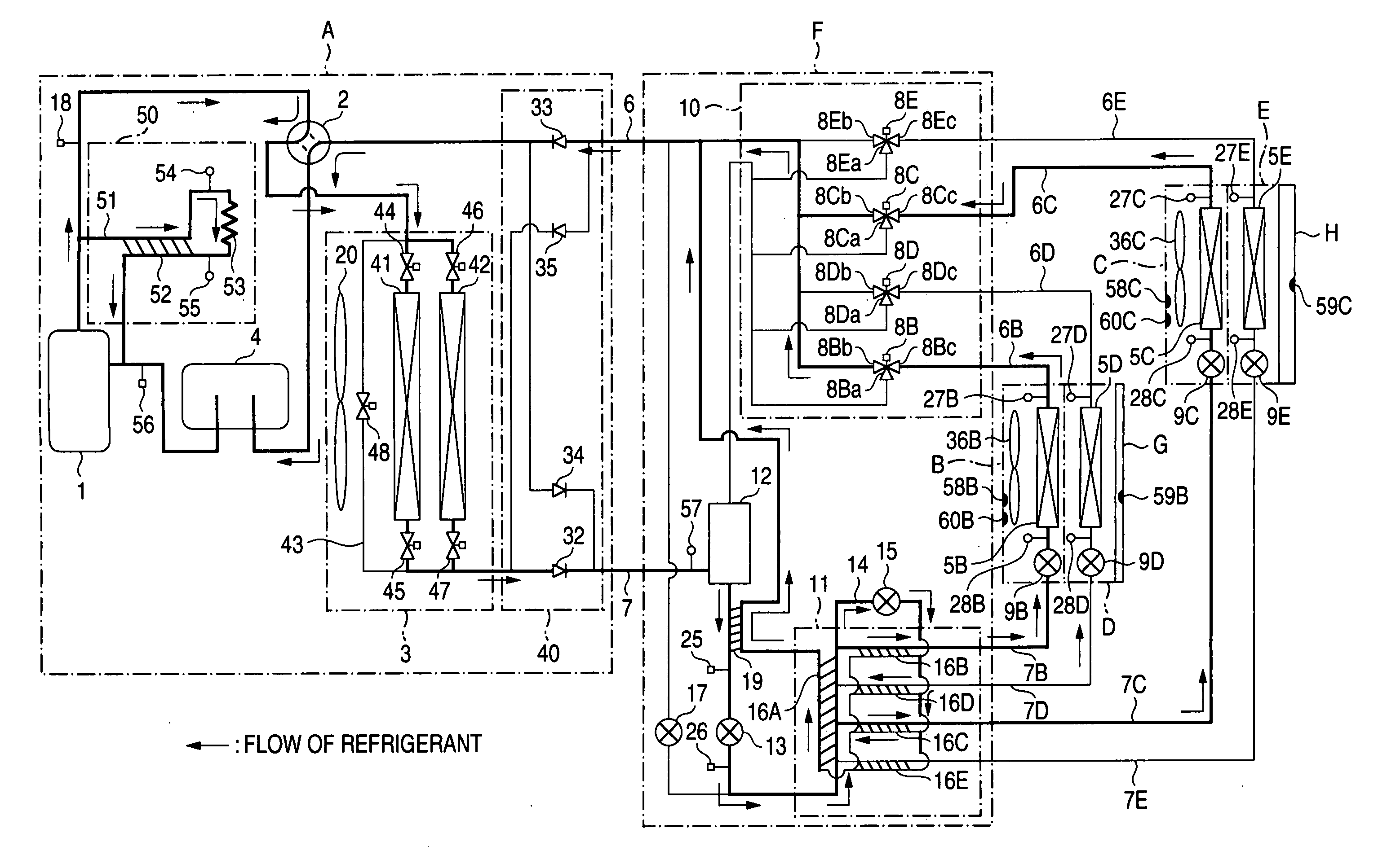
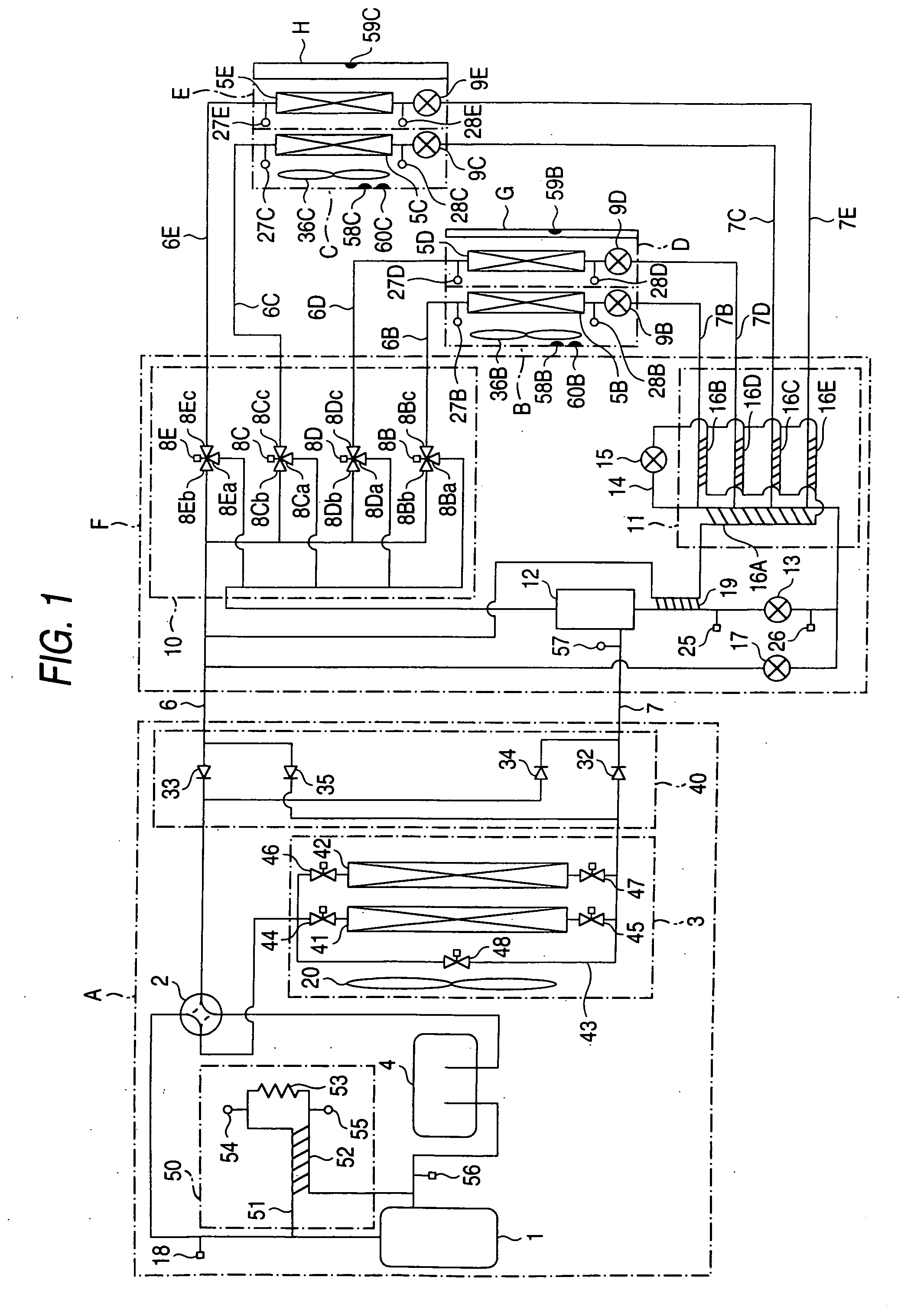
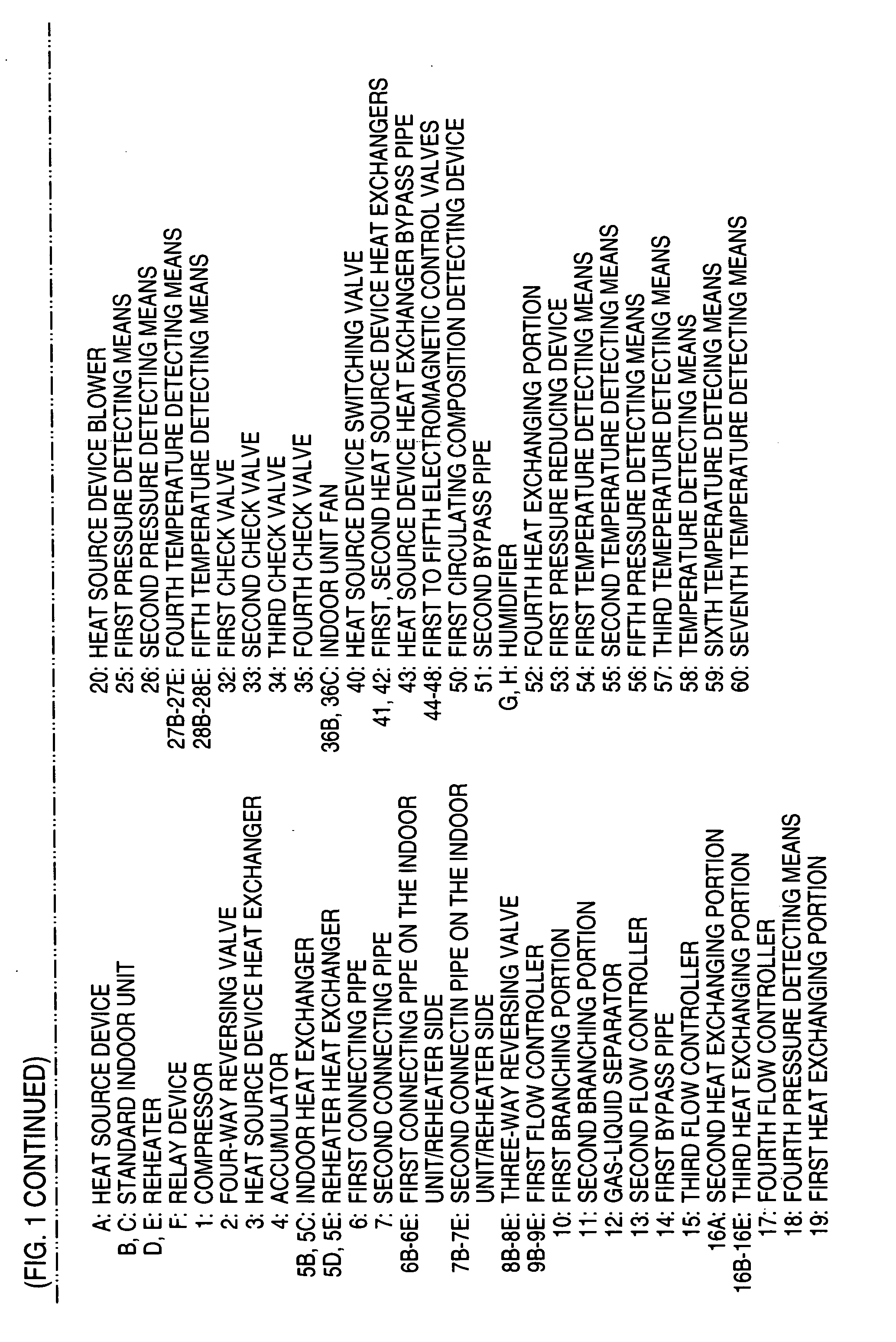
[0033]FIG. 1 is a refrigerant circuit diagram of an air conditioning apparatus of Embodiment 1 of the invention.

[0034] Referring to FIG. 1, the air conditioning apparatus is mainly configured by connecting a heat source device (A), a first indoor unit comprising: a standard indoor unit (B); a reheater (D); and a humidifier (G), a second indoor unit comprising: a standard indoor unit (C); a reheater (E); and a humidifier (H), and a relay device (F) through refrigerant pipes.

[0035] Although the configuration in which two indoor units are used will be described, the number of indoor units is not restricted to two, and any number of indoor units may be used.

[0036] The heat source device (A) is mainly configured by connecting a variable capacity compressor 1, a four-way reversing valve 2 which switches over refrigerant flowing directions of the heat source device, a heat source device heat exchanger 3, an accumulator 4, a heat source device switching valve 40, and a first circulating ...

embodiment 2

[0139]FIG. 20 is a refrigerant circuit diagram of an air conditioning apparatus of Embodiment 2 of the invention. In a type in which a heat source device is connected to relay devices through three pipes, cooling / heating / temperature and humidity air conditioning of plural indoor units can be individually controlled. Although the configuration in which two standard indoor units, two reheaters, and two humidifiers are connected to one heat source device will be described with reference to FIG. 20, the number of such units is not restricted to two, and any number of units may be used. The manner of connecting the standard indoor units, the reheaters, and the humidifiers, and the method of controlling the indoor units are identical with those shown in FIGS. 12 to 19.

[0140] Referring to FIG. 20, a relay device (F1) is configured so as to connect the first pipe 6, the second pipe 7, and a third pipe 104 to the two pipes of the standard indoor unit (B), a relay device (F2) is configured s...


PUM


Abstract

An air conditioning apparatus has plural indoor units having: plural heat exchangers; and flow controllers respectively corresponding to the heat exchangers. In each of the indoor units, one heat exchanger is used as a condenser, and another heat exchanger is used as an evaporator, thereby causing the indoor unit to perform a temperature and humidity controlling operation. An indoor unit(s) which is not set to perform the temperature and humidity controlling operation may be caused to perform a heating operation or a cooling operation. Capacity controls on the condensers and the evaporators are performed by corresponding flow controllers. Gas refrigerants ejected from plural heat exchangers serving as evaporators are joined together, and then distributed to plural heat exchangers serving as condensers.

Description

TECHNICAL FIELD [0001] The present invention relates to an air conditioning apparatus which has an outdoor unit and plural indoor units, and which can perform cooling and heating operations. BACKGROUND ART [0002] JP-A-5-99525 and JP-A-2000-105014 disclose a simultaneous cooling / heating type air conditioning apparatus in which a heat source device is connected to plural indoor units through refrigerant pipes, and each of the indoor units can perform cooling and heating operations. [0003] JP-A-2002-89988 discloses an air conditioning apparatus in which one heat source device is connected to one indoor unit through refrigerant pipes, and two heat exchangers are connected to the indoor unit via a flow control valve, and which can perform a cooling operation, a heating operation, a cooling, reheating, and dehumidifying operation, and a heating, reheating, and dehumidifying operation. [0004] However, the air conditioning apparatuses of JP-A-5-99525 and JP-A-2000-105014 have a problem in t...

Claims


Application Information

Patent Timeline
Patent Type & Authority Applications(United States)
IPC IPC(8): F25B27/00F25B13/00F24F3/06F24F3/153F25B29/00
CPCF24F3/065F24F3/153F24F2221/54F25B13/00F25B2313/006F25B2313/007F25B2700/02F25B2313/0233F25B2313/02333F25B2313/02531F25B2313/02791F25B2400/05F25B2600/0261F25B2313/0231
Inventor SHIMAMOTO, DAISUKEYAMANAKA, MUNEHIROTANI, HIDEKAZUKASAI, TOMOHIKOTSUDA, MASAHIROOURA, SHUJISAITOU, MAKOTO
Owner MITSUBISHI ELECTRIC CORP
Why Eureka
Try Eureka