Switch mechanism and electronic apparatus

a technology of electronic equipment and switch mechanism, which is applied in the direction of electronic switching, pulse technique, instruments, etc., can solve the problems of component parts assembly errors, tendency toward, and accumulation of dimensional dispersion of components, so as to enhance the reliability of switching operations

Inactive Publication Date: 2006-11-16
SONY CORP
View PDF4 Cites 5 Cited by
  • Summary
  • Abstract
  • Description
  • Claims
  • Application Information

AI Technical Summary

Benefits of technology

[0020] With the magnifying mechanism adopted, the reliability of the switching operations is enhanced. Besides, the mounting accuracy and restrictive conditions required on the side of a housing to which the switch mechanism is attached can be moderated.

Problems solved by technology

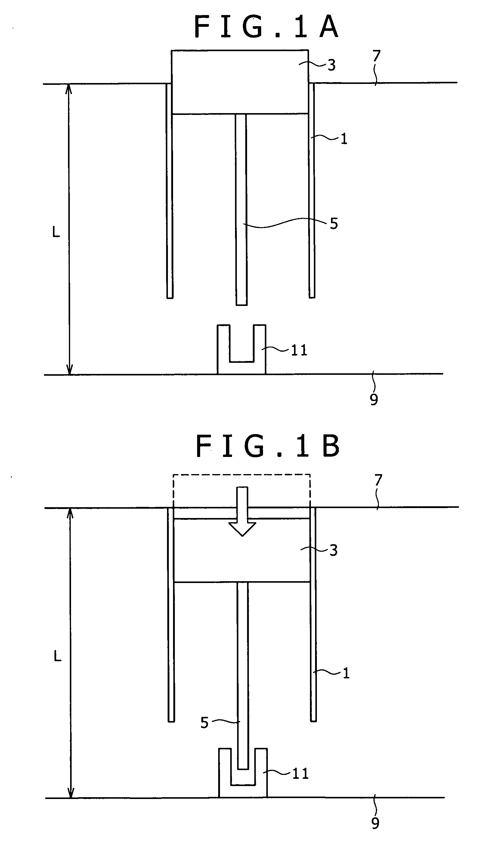
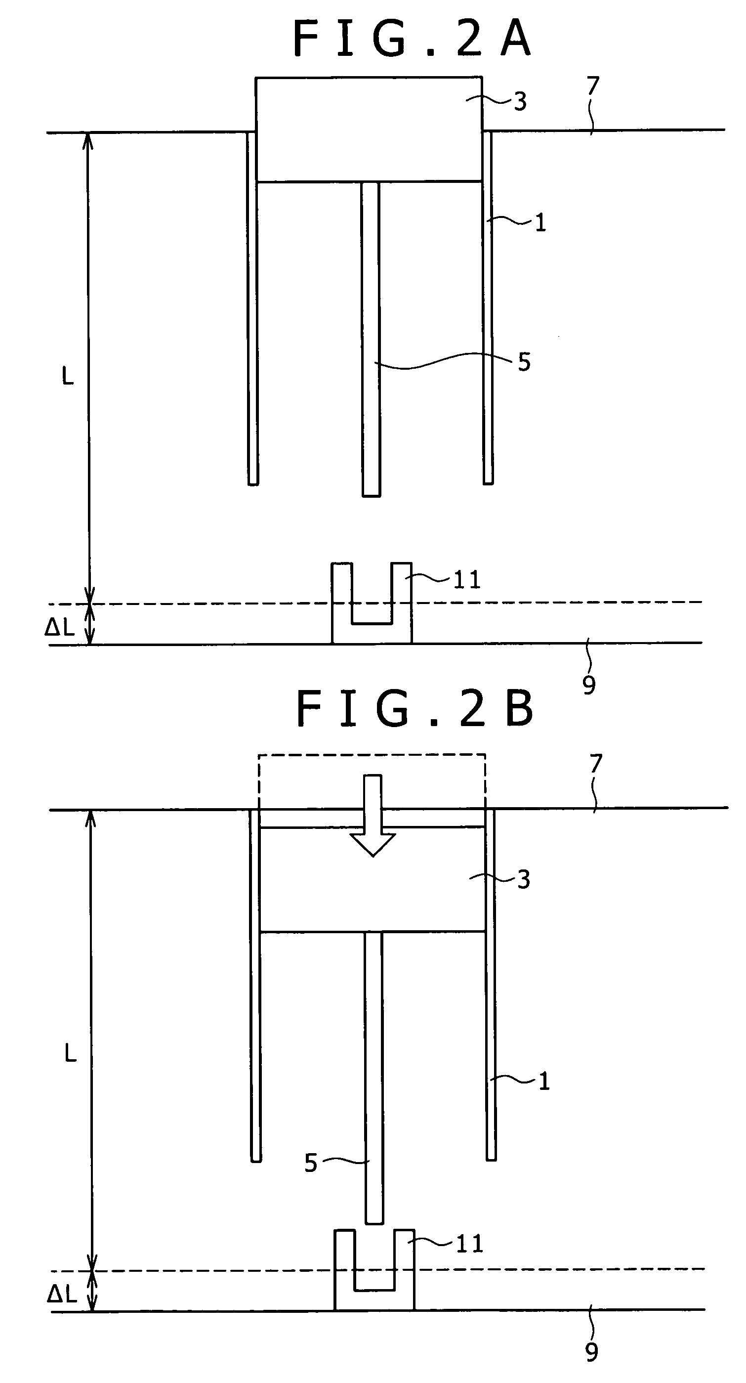
Therefore, there is a tendency toward accumulation dimensional dispersions of the component parts, assembly errors of the component parts, mounting errors of the detection sensor, etc.
In particular, where deviations in the vertical direction (the direction in which the drive mechanism and the detection sensor on the wiring board are away from each other) are present, there is the possibility that the tip end of the shaft 5 may not reach the position of the detection sensor even when the button top is depressed.

Method used


Image

  • Switch mechanism and electronic apparatus
  • Switch mechanism and electronic apparatus
  • Switch mechanism and electronic apparatus

Examples


Embodiment Construction

[0032] Now, an embodiment of a switch mechanism of a detection sensor unmounted type and a control panel according to the technique pertaining to the present invention will be described below.

[0033] It is to be noted that known technologies in the art pertaining to the invention are applied to the portions not specifically shown in the drawings or described in this specification.

[0034] Besides, the embodiment described below is merely an embodiment of the present invention, and the invention is not limited to or by the embodiment.

(A) Control Panel

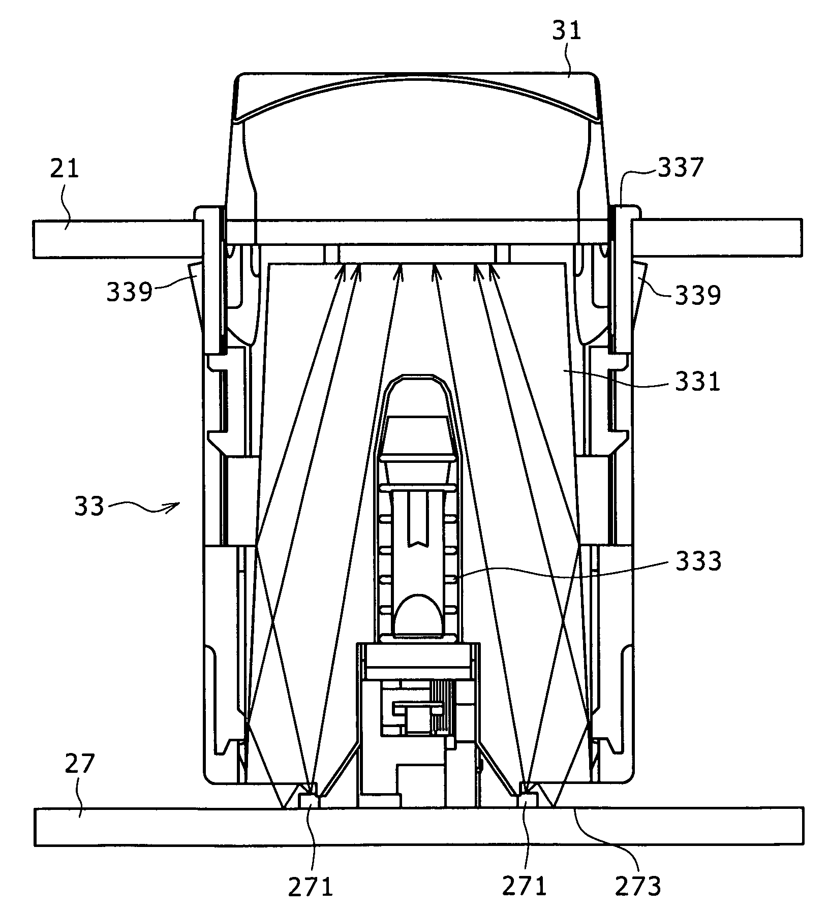
[0035]FIG. 3 illustrates an example of a control panel for a live switcher. FIG. 3 corresponds to an operating surface of the control panel 21. Operating buttons 23 are arranged in a number of stages on the control panel 21. By operating the operating buttons 23, it is possible to perform switching of signals to be connected, turning ON / OFF of various functions, switching of mode, and the like operations.

[0036]FIG. 4 illustrates the fa...


PUM


Abstract

A switch mechanism of a detection sensor unmounted type has a configuration in which an attaching surface for a case body for containing a movable member moved in conjunction with a button operation and a mounting surface for a detection sensor operative to electrically detect a change in the position of the movable member attendant on the button operation are different, and a magnifying mechanism operative to magnifyingly transmit the change in the position of the movable member attendant on the button operation is mounted in the switch mechanism.

Description

CROSS REFERENCES TO RELATED APPLICATIONS [0001] The present invention contains subject matter related to Japanese Patent Application JP 2005-142607 filed with the Japanese Patent Office on May 16, 2005, the entire contents of which being incorporated herein by reference. BACKGROUND OF THE INVENTION [0002] The present invention, in its one embodiment, relates to a switch mechanism of a type in which a detection sensor containing a movable member moved in conjunction with a button operation is not mounted. In another embodiment, the present invention relates to an electronic apparatus wherein the switch mechanism of the type in which the detection sensor is not mounted is attached to an operating surface. [0003] In contents production sites and output sites, a large number of material data and program data are dealt with daily. For example, in a contents production site, a multiplicity of material data are dealt with in an editing work. Also, in a contents output site, in addition to ...

Claims


Application Information

Patent Timeline
Patent Type & Authority Applications(United States)
IPC IPC(8): H01H9/00
CPCH01H13/023H03K17/975H03K17/97H01H9/18H01H13/70
Inventor TSUBOTA, TETSUROKOUDA, ATSUSHI
Owner SONY CORP
Why Eureka
Try Eureka