Imprint templates for imprint lithography, and methods of patterning a plurality of substrates

a technology of imprint lithography and templates, which is applied in the direction of photomechanical equipment, instruments, manufacturing tools, etc., can solve the problems of reducing the minimum feature size of the circuit device using photolithography, and if the equipment enabling such photolithography will be cost prohibitive, so as to reduce the elevation of spaced features

Active Publication Date: 2006-11-16
MICRON TECH INC
View PDF17 Cites 61 Cited by
  • Summary
  • Abstract
  • Description
  • Claims
  • Application Information

AI Technical Summary

Benefits of technology

[0006] The invention comprises methods of patterning a plurality of substrates, and comprises imprint templates used in imprint lithography. In one implementation, a method of patterning a plurality of substrates includes providing an imprint template having a plurality of spaced features. A first substrate is imprinted with the imprint template effective to form a plurality of recesses into the first substrate from the spaced features. After imprinting the first substrate, an elevationally outermost portion of the spaced features is removed effective to reduce elevation of the spaced features. After the removing, a second substrate is imprinted with the imprint template using the elevation-reduced spaced features effective to form a plurality of recesses into the second substrate from the elevation-reduced spaced features.

Problems solved by technology

The use of progressively shorter wavelengths of the incident radiation, along with increased complexity in the photomasks, has continually led to a reduction of the minimum feature size of the circuit devices using photolithography.
However, it remains to be seen whether the equipment enabling such photolithography will be cost prohibitive.

Method used


Image

  • Imprint templates for imprint lithography, and methods of patterning a plurality of substrates
  • Imprint templates for imprint lithography, and methods of patterning a plurality of substrates
  • Imprint templates for imprint lithography, and methods of patterning a plurality of substrates

Examples


Embodiment Construction

[0029] This disclosure of the invention is submitted in furtherance of the constitutional purposes of the U.S. Patent Laws “to promote the progress of science and useful arts” (Article 1, Section 8).

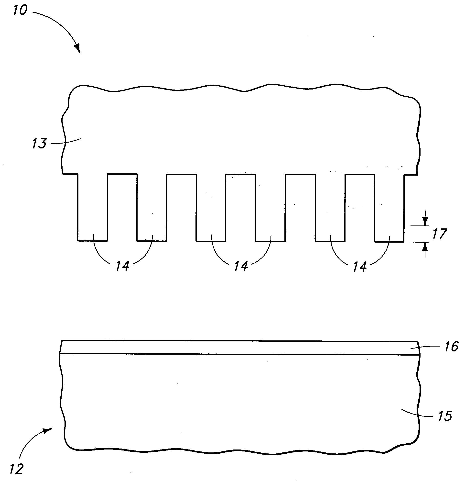
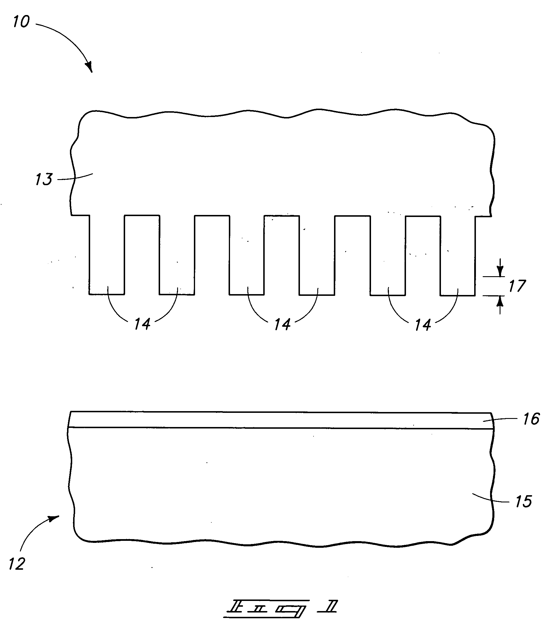
[0030] An exemplary method of patterning a plurality of substrates is described initially with reference to FIGS. 1-6. FIG. 1 depicts an imprint template 10 and a first substrate 12 which will be imprinted upon. In the context of this document, an “imprint template” is any template used for conducting an imprinting operation wherein a plurality of recesses is formed into a substrate by the physical imprinting engagement of the template with another substrate. Exemplary imprint template 10 is comprised of a material 13, and has a plurality of spaced features 14 provided therein. By way of example only, such are depicted in the FIG. 1 embodiment as comprising identically shaped and dimensioned structures, although such is of course not required. Further by way of example only, particularl...


PUM

PropertyMeasurementUnit
wavelengthaaaaaaaaaa
widthaaaaaaaaaa
widthaaaaaaaaaa

Abstract

The invention comprises methods of patterning a plurality of substrates, and imprint templates used in imprint lithography. In one implementation, a method of patterning a plurality of substrates includes providing an imprint template having a plurality of spaced features. A first substrate is imprinted with the imprint template effective to form a plurality of recesses into the first substrate from the spaced features. After imprinting the first substrate, an elevationally outermost portion of the spaced features is removed effective to reduce elevation of the spaced features. After the removing, a second substrate is imprinted with the imprint template using the elevation-reduced spaced features effective to form a plurality of recesses into the second substrate from the elevation-reduced spaced features. Other aspects and implementations are contemplated.

Description

TECHNICAL FIELD [0001] This invention relates to methods of patterning a plurality of substrates, and to imprint templates used in imprint lithography. BACKGROUND OF THE INVENTION [0002] Integrated circuits are typically fabricated onto and within semiconductor substrates, with the continuing trend being towards ever-smaller devices and circuitry. The key to this progress has been microlithography which has been used to create micron- and submicron-scale structures for fabricating various devices of the integrated circuits. For decades, microlithography has been dominated by the use of light and photosensitive material to etch or otherwise pattern structures and regions relative to an underlying semiconductor substrate. Such is commonly referred to as photolithography, whereby the details of a particular circuit layer can be projected from a photomask onto photosensitive material on the substrate. The use of progressively shorter wavelengths of the incident radiation, along with inc...

Claims


Application Information

Patent Timeline
Patent Type & Authority Applications(United States)
IPC IPC(8): B28B11/08C03C15/00A01K1/015
CPCB82Y10/00G03F7/0002B82Y40/00Y10S977/887Y10T428/249921
Inventor SANDHU, GURTEJ S.CHANCE, RANDAL W.
Owner MICRON TECH INC
Why Eureka
Try Eureka