Transfer apparatus and transfer method

a technology of transfer apparatus and transfer method, which is applied in the direction of load-engaging elements, safety gear, cranes, etc., can solve the problems of further shift of the unloading position of the article, inclination detection,

Inactive Publication Date: 2011-03-10
MURATA MASCH LTD
View PDF2 Cites 5 Cited by
  • Summary
  • Abstract
  • Description
  • Claims
  • Application Information

AI Technical Summary

Benefits of technology

[0005]Preferred embodiments of the present invention make it possible to transfer an article whi

Problems solved by technology

However, in the case of reading the mark near the support member, areas where inclination can be detected are limited to narrow ranges immediately before a loading position and immediately before an unloading position.
Further, since no s

Method used


Image

  • Transfer apparatus and transfer method
  • Transfer apparatus and transfer method
  • Transfer apparatus and transfer method

Examples


Embodiment Construction

[0024]Hereinafter, preferred embodiments for carrying out the present invention in the most preferred form will be described. The scope of the present invention shall be determined according to the understanding of a person skilled in the art based on the description of the claims in consideration of the description of the specification and techniques known in this technical field.

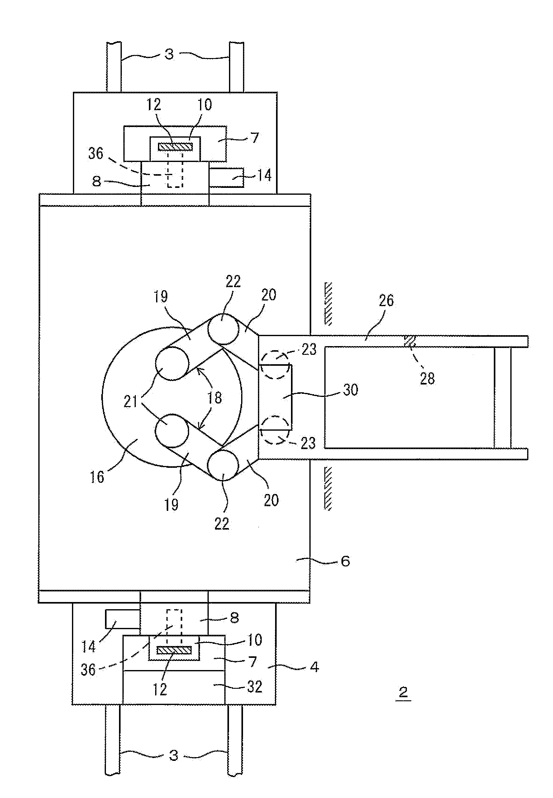
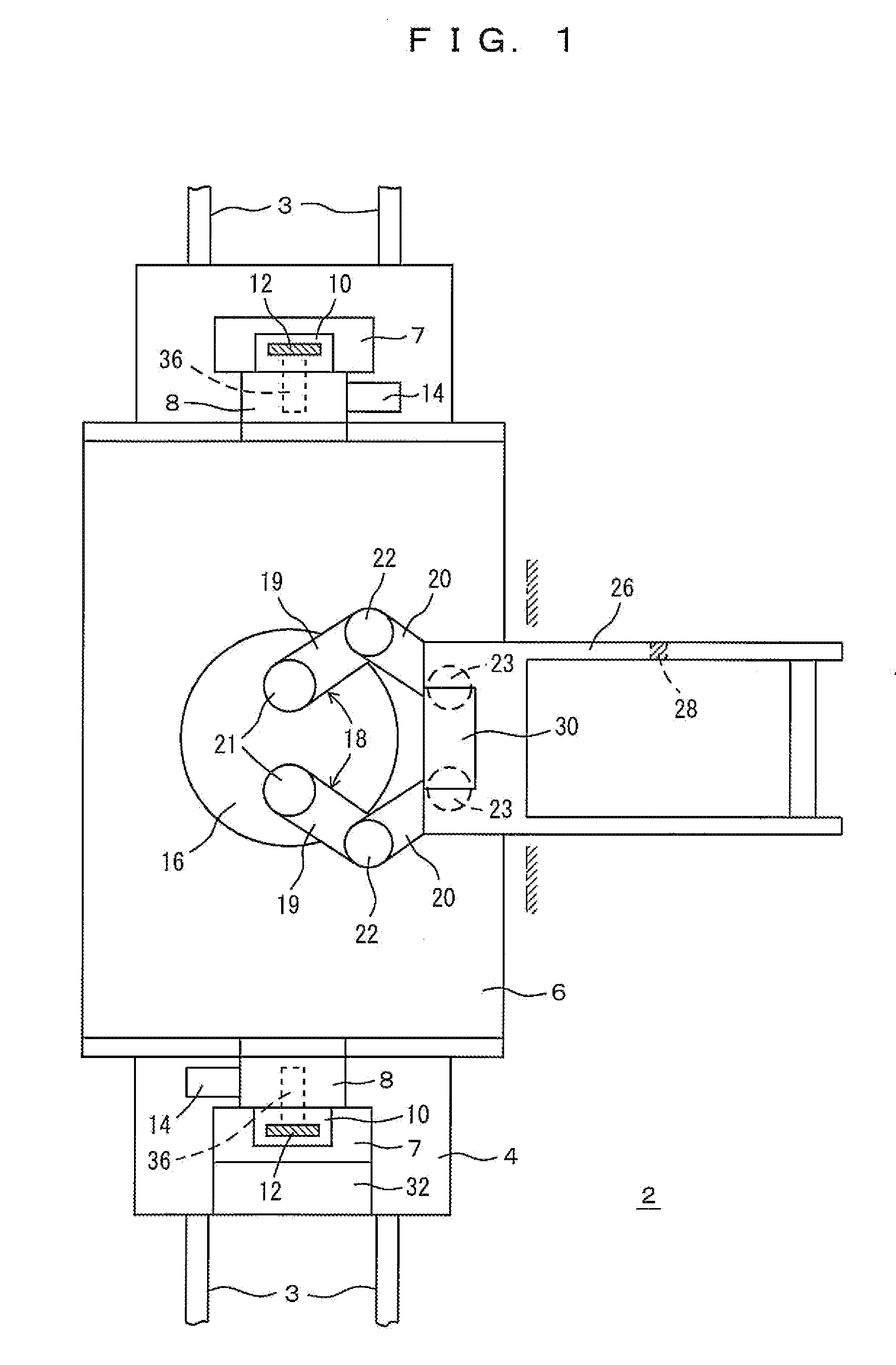
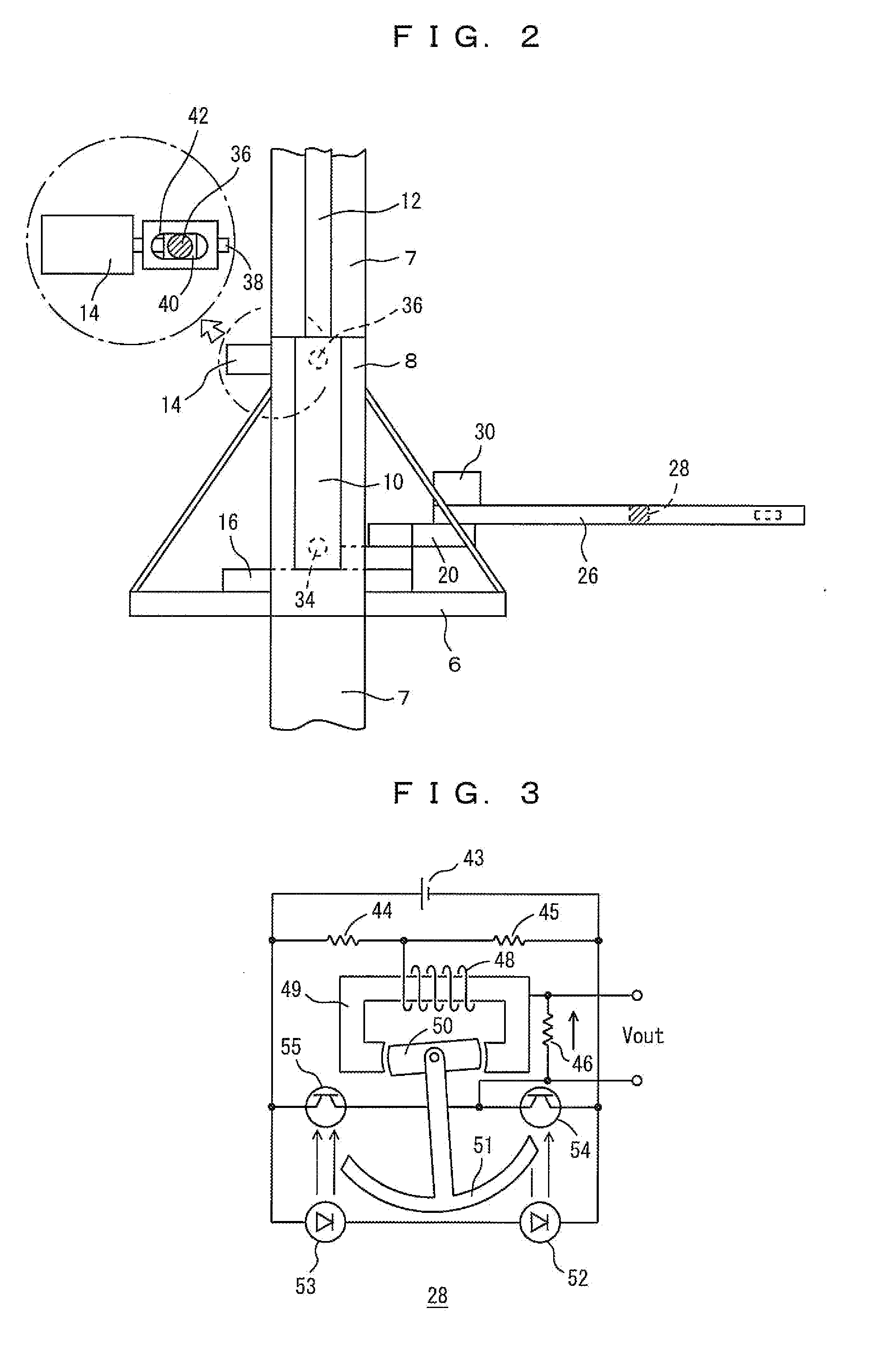
[0025]FIGS. 1 to 7 show a stacker crane 2 taken as an example of a transfer apparatus according to a preferred embodiment of the present invention. A transfer apparatus according to a preferred embodiment of the present invention may be mounted in an automatic transportation vehicle, an overhead traveling vehicle or the like, for example. Alternatively, instead of mounting the transfer apparatus in the vehicle, a body of the transfer apparatus may be attached to a tiltable base provided on a station or the like, for example. In the drawings, a reference numeral 2 denotes a stacker crane that travels on tra...


PUM


Abstract

In a transfer apparatus, a SCARA arm is provided on an elevation platform. Further, a sensor arranged to detect inclination at a tip end of the arm and a sensor arranged to measure a position of an article on the arm are provided. A base is tilted to eliminate inclination of the detected inclination, and a stretching amount of the arm is corrected in correspondence with the measured position of the article on the arm.

Description

BACKGROUND OF THE INVENTION[0001]1. Field of the Invention[0002]The present invention relates to a transfer apparatus. In particular, the present invention relates to a transfer apparatus capable of unloading an article to a predetermined position without any inclination of an arm at a time of stretching the arm.[0003]2. Description of the Related Art[0004]The applicant proposed to attach an optical sensor to a tip end of an arm of a slide fork or the like, for reading a mark near a support member to correct inclination of the arm. See, for example, JP 2006-219233A. However, in the case of reading the mark near the support member, areas where inclination can be detected are limited to narrow ranges immediately before a loading position and immediately before an unloading position. In other positions, inclination can only be corrected by means of an open loop control in accordance with a stored pattern. Under such circumstances, since inclination of the arm cannot be corrected suffic...

Claims


Application Information

Patent Timeline
IPC IPC(8): B66C13/18
CPCB66C13/46B66C13/18
Inventor KUMAZAWA, TSUYOSHIHATTORI, MASARUMURAKAMI, TAKESHI
Owner MURATA MASCH LTD
Why Eureka
Try Eureka