
Display device

Active Publication Date: 2006-11-16
PANASONIC LIQUID CRYSTAL DISPLAY CO LTD +1
View PDF10 Cites 41 Cited by
  • Summary
  • Abstract
  • Description
  • Claims
  • Application Information

AI Technical Summary

Benefits of technology

[0009] An object of the present invention is to provide a display device for displaying a plurality of display data in one frame period, the display device being capable of reducing moving image blurring and improving a moving image quality, by reducing a delay in a pixel response speed and an insufficient luminance to be caused by shortening a write period of a display signal.
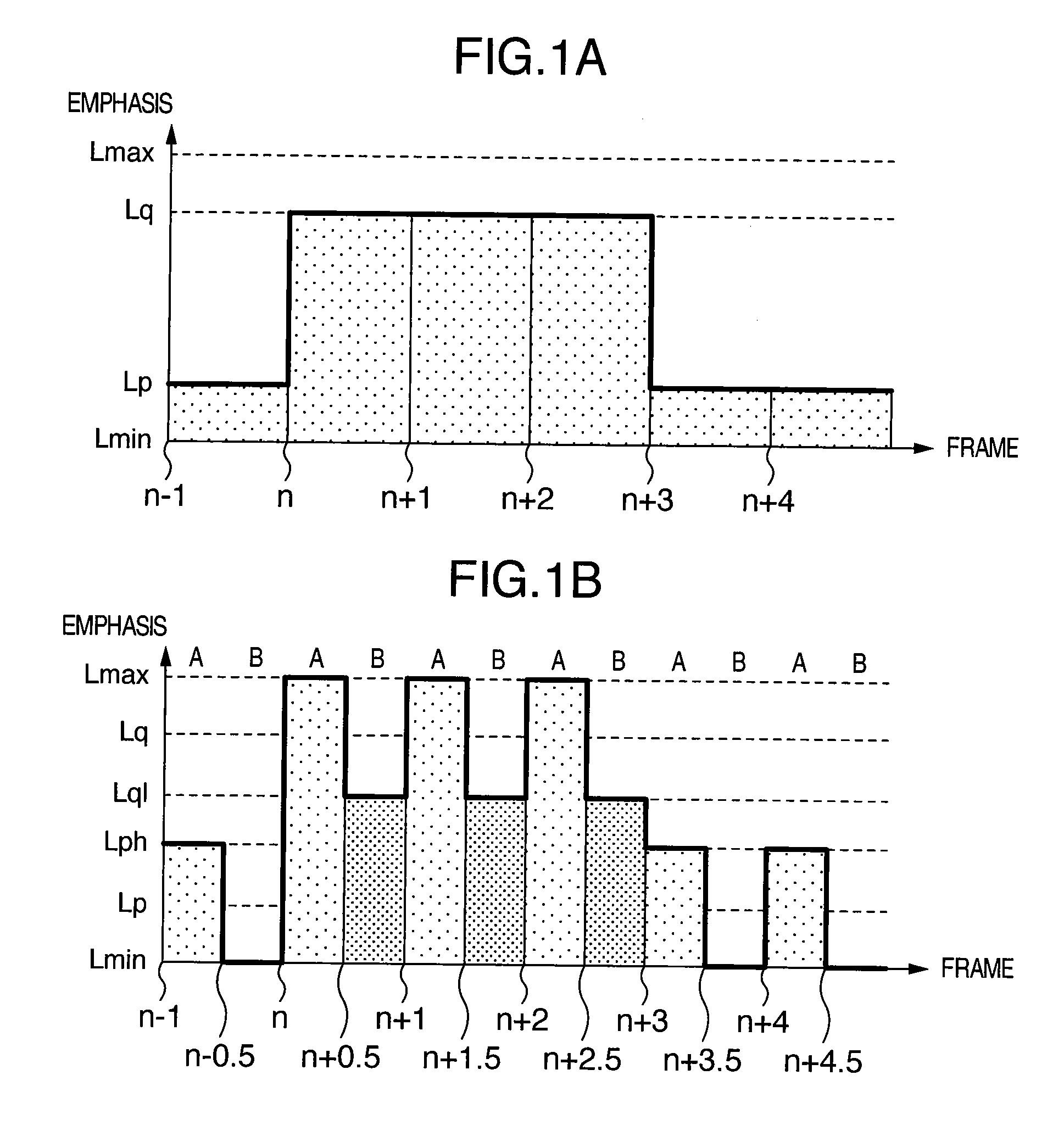
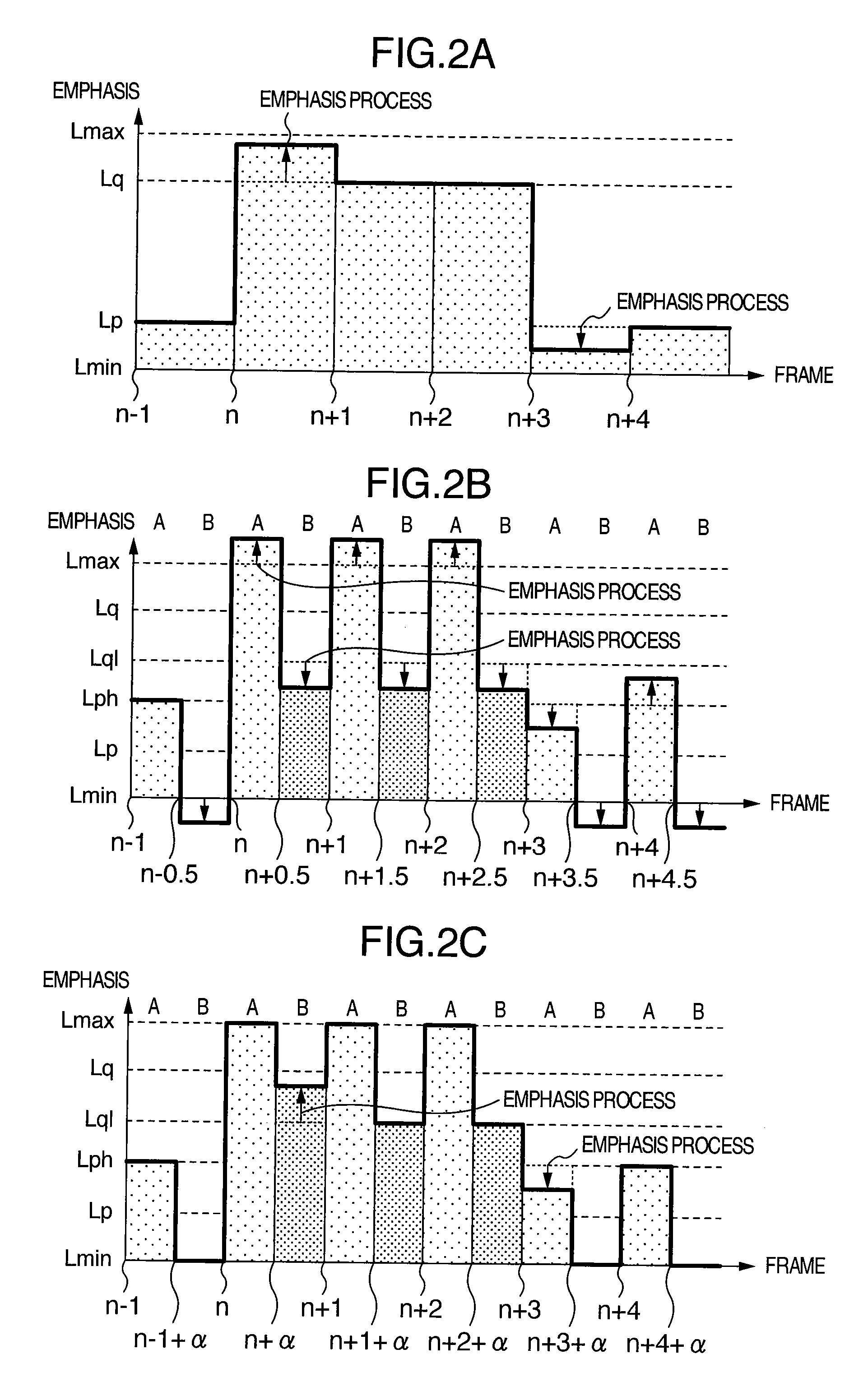
[0012] According to the present invention, in the display device for displaying a plurality of display data in one frame period, it is possible to reduce moving image blurring and improve a moving image quality, by reducing a delay in a pixel response speed and an insufficient luminance to be caused by shortening a write period of a display signal. In other words, by applying the frame division drive to a hold-type display device, it becomes possible to realize the optical emission characteristics of an impulse type display device and obtain a good display quality with less moving image blurring. By using the emphasis drive, it becomes possible to shorten a time required for an apparent luminance response and obtain a good display quality with less moving image blurring.
[0013] According to the present invention, in a display device provided with the frame division drive and emphasis drive, a good display quality can be obtained while pseudo contour lines and color shift are suppressed, by controlling the emphasis drive separately for each of frame-divided fields.

Problems solved by technology

In this case, the emphasis drive cannot be applied to the highest gray-scale field, because emphasis in excess of the highest gray-scale is impossible.
In this case, the emphasis drive cannot be applied to the lowest gray-scale field, because emphasis lower than the lowest gray-scale is impossible.
As described above, it is difficult to apply the emphasis drive simply to the frame division drive.

Method used


Image

  • Display device
  • Display device
  • Display device

Examples


second embodiment

[0102] In the following, the second embodiment of the present invention will be described with reference to FIGS. 7 and 8.

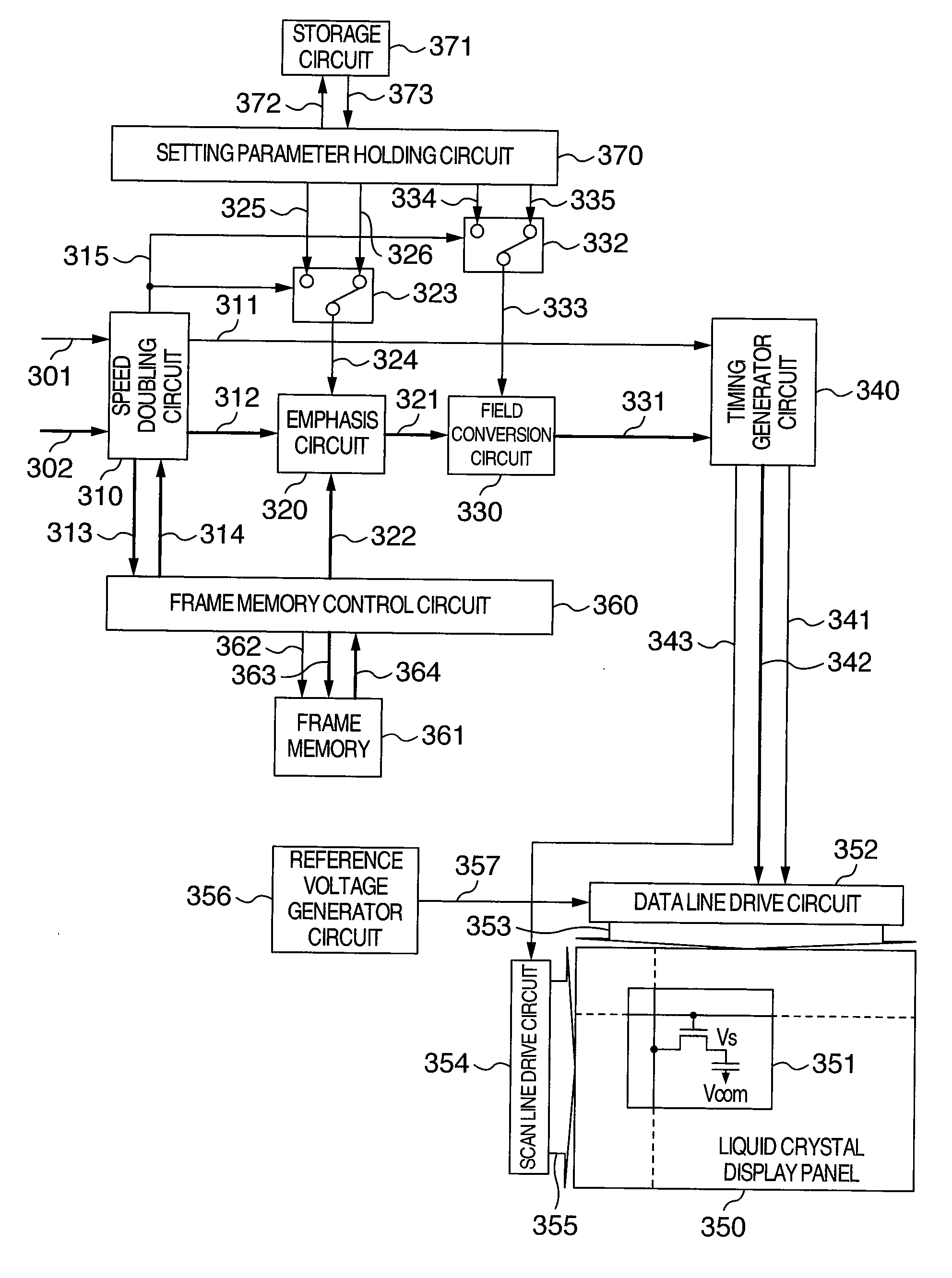
[0103]FIG. 7 is a diagram showing an example of the structure of a display device according to the second embodiment of the present invention. FIG. 8 is a diagram illustrating an example of the operation of the display device according to the second embodiment of the present invention, and showing a timing chart of the display device shown in FIG. 7. In the second embodiment, the structures having identical reference numerals to those of the first embodiment are the same as those of the first embodiment. In the following, the second embodiment will be described mainly on different points from the first embodiment.

[0104] The emphasis circuit 320 receives input display data 302, and instructs the frame memory control circuit 360 to read input display data one frame before the input display data 302 from the frame memory 361 synchronously with an input of the inpu...


PUM


Abstract

A speed doubling circuit receiving display data in one frame period and outputting field A display data and field B display data in one frame period. A field conversion circuit converts the field A display data to have a highest gray-scale if the display data has a high gray-scale, and converts the field B display data to have a lowest gray-scale if the display data has a low gray-scale. Between the speed doubling circuit and field conversion circuit, an emphasis circuit is disposed which emphasizes each of the field A display data and field B display data in accordance with the display data one frame period before and the display data in the present frame period.

Description

INCORPORATION BY REFERENCE [0001] The present application claims priority from Japanese applications JP 2005-137986 filed on May 11, 2005, and JP 2005-229008 filed on Aug. 8, 2005, the contents of which are hereby incorporated by reference into this application. BACKGROUND OF THE INVENTION [0002] The present invention relates to a hold-type display device such as a liquid crystal display device, an organic electro luminance (EL) display and a liquid crystal on silicon (LCOS) display and its driving method, and more particularly to a display device suitable for displaying moving images and its driving method. [0003] Display devices are mainly classified into an impulse type display device and a hold-type display device if the display devices are classified from the viewpoint of moving image display. The impulse type display device is a device like a Brown tube of the type that pixels become bright only during a scanned period and a luminance of each pixel lowers immediately after sca...

Claims


Application Information

Patent Timeline
IPC IPC(8): G09G5/10
CPCG09G3/2022G09G3/3688G09G2340/16G09G2320/0261G09G2320/0276G09G2320/0252G09G3/20G09G3/30G09G3/36G02F1/133
Inventor MARUYAMA, JUNICHINITTA, HIROYUKIOOISHI, YOSHIHISAONO, KIKUO
Owner PANASONIC LIQUID CRYSTAL DISPLAY CO LTD
Learn More