Display device

a display device and display technology, applied in the field of hold-response type display devices, can solve the problems of affecting the display quality, so as to reduce the blurring of the moving image, suppress the lowering of brightness, and the effect of lowering contras

Inactive Publication Date: 2009-08-13
PANASONIC LIQUID CRYSTAL DISPLAY CO LTD +1
View PDF5 Cites 2 Cited by
  • Summary
  • Abstract
  • Description
  • Claims
  • Application Information

AI Technical Summary

Benefits of technology

[0020]According to the display device of the present invention, in the hold-response-type display device, it is possible to reduce moving image blurring while suppressing lowering of brightness, lowering of contrast and the increase of electric power necessary for light emission.
[0021]Further, in the hold-response-type display device, it is possible to perform a smooth gradation display while reducing moving image blurring.

Problems solved by technology

However, in displaying a moving image, there arises so-called moving image blurring in which a periphery of a moving object is blurred thus giving rise to a drawback that display quality is remarkably lowered.
Accordingly, in the hold-response-type display device, even when a response speed is enhanced as fast as possible, it is impossible to completely eliminate the moving image blurring.
Although the moving image blurring can be overcome by applying the above-mentioned techniques to the hold-response-type display, there has been known that the following drawbacks arise due to the application of such techniques.
On the other hand, when the circuit scale is suppressed, generation errors occur in the display data of the interpolation frame thus giving rise to a possibility that display quality is remarkably deteriorated.
When the brightness of a backlight is increased in the black display data insertion method for compensating for the lowered amount of brightness, for example, the power consumption is increased correspondingly and, at the same time, considerable time and efforts become necessary to cope with the generation of heat.

Method used


Image

  • Display device
  • Display device
  • Display device

Examples


embodiment

[0062]FIG. 4 is a schematic graph showing one example of a display method performed by the display device of one embodiment according to the present invention.

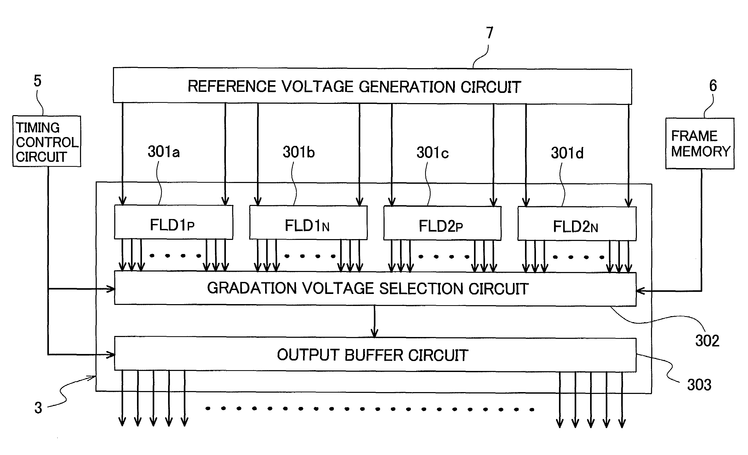
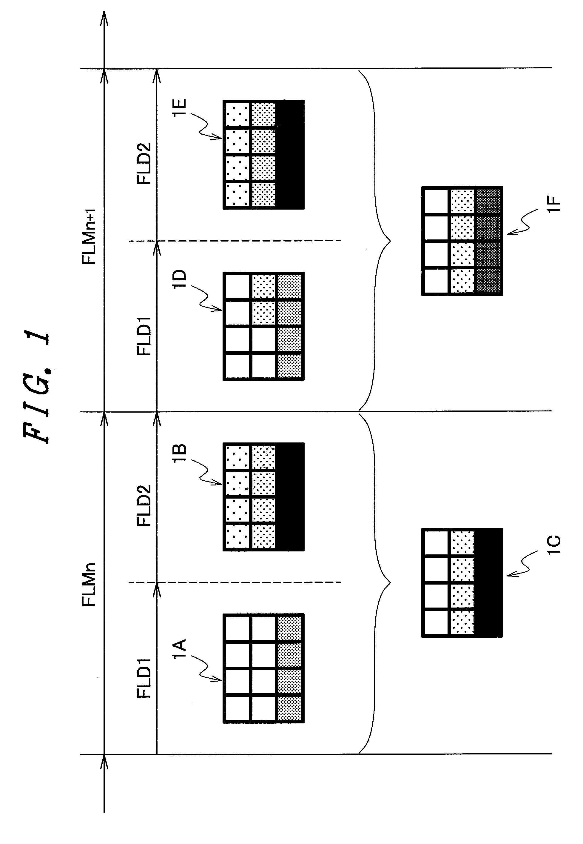
[0063]The present invention uses the display device having the constitution shown in FIG. 3A to FIG. 3D and, for example, as shown in FIG. 1 and FIG. 2, the display data amounting to 1 frame period is displayed by dividing 1 frame period into the first field period FLD1 and the second field period FLD2.

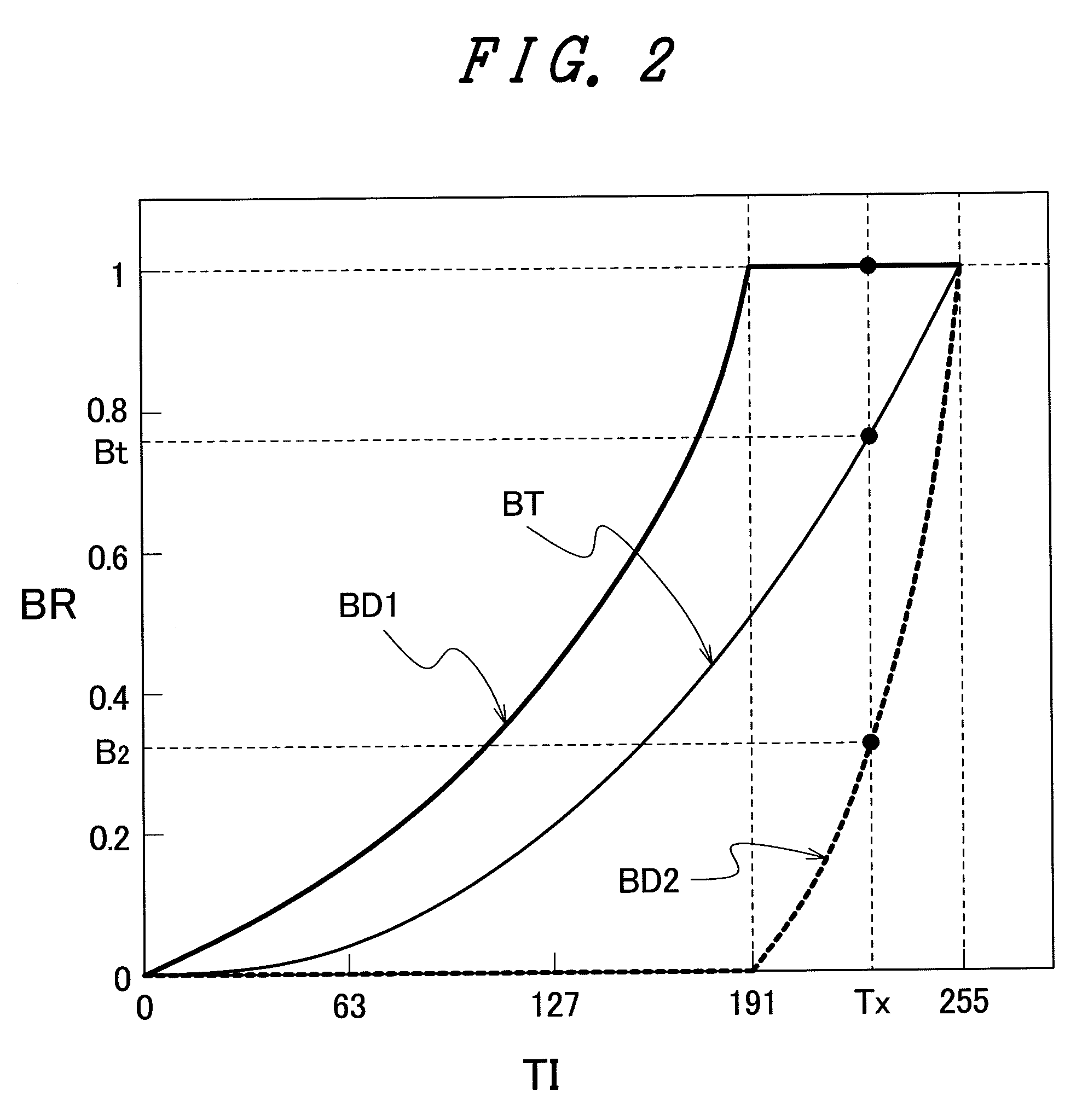
[0064]Here, by allowing the brightness curve BD1 of the display data to be displayed during the first field period FLD1 to exhibit the distribution shown in FIG. 2, for example, a range of brightness from the brightness of the minimum gradation (0th gradation) to the brightness of the maximum gradation (255th gradation) which is divided into 256 stages in the conventional display device is divided into approximately 192 stages (gradations). Accordingly, for example, the difference of the gradation voltage (relative brightness) b...


PUM


Abstract

The present invention reduces moving image blurring while suppressing the lowering of brightness, lowering of contrast and the increase of electricity necessary for light emission. A display device includes a first gradation voltage generation circuit which generates a first gradation voltage based on gradations of display data amounting to 1 screen displayed during 1 frame period, and a second gradation voltage generation circuit which generates a second gradation voltage based on the gradations of display data amounting of 1 screen displayed in 1 frame period, wherein the gradations of the respective pixels on the display data are displayed by performing a display based on the first gradation voltage and a display based on the second gradation voltage during 1 frame period. The first gradation voltage generation circuit and the second gradation voltage generation circuit respectively include a resistance voltage dividing circuit which is formed by connecting a plurality of resistances in series. In a region of the resistance voltage driving circuit of the first gradation voltage generation circuit where a plurality of resistances having a substantially fixed resistance value are continuously formed, a resistance of the resistance voltage dividing circuit of the second gradation voltage generation circuit is changed from a value lower than the resistance value of the resistance voltage dividing circuit of the first gradation voltage generation circuit to a value higher than the resistance value of the resistance voltage dividing circuit of the first gradation voltage generation circuit.

Description

[0001]The present application claims priority from Japanese application JP2006-247454 filed on Sep. 13, 2006, the content of which is hereby incorporated by reference into this application.BACKGROUND OF THE INVENTION[0002]1. Field of the Invention[0003]The present invention relates to a hold-response-type display device such as a liquid crystal display or an organic EL (electro-luminescence) display.[0004]2. Description of the Related Art[0005]Conventionally, in classifying a display device such as a display for a television receiver set or a personal computer (PC) from a viewpoint of moving image display, the display device is roughly classified into an impulse-response-type display device and a hold-response-type display device. The impulse-response-type display device is a display device of a type in which a brightness response is lowered immediately after scanning as in the case of afterglow characteristic of a cathode ray tube, for example. Further, the hold-response-type displ...

Claims


Application Information

Patent Timeline
Patent Type & Authority Applications(United States)
IPC IPC(8): G09G5/10
CPCG09G3/2025G09G3/2081G09G3/3648G09G2360/18G09G2310/027G09G2320/0261G09G3/3696
Inventor ENDO, KENTAOOISHI, YOSHIHISA
Owner PANASONIC LIQUID CRYSTAL DISPLAY CO LTD
Why Eureka
Try Eureka