Spectacles set with decorative frame

a technology of decorative frames and spectacles, applied in the field of spectacles, can solve the problems of wearing one set of fashionable spectacles, wearing only the two surfaces of each of the lenses, and the conventional spectacles are difficult to clean in detail, so as to achieve the effect of simple detachable mounting operation of the lens, low cost and reduced cos

Inactive Publication Date: 2006-11-16
LI XIN LIANG
View PDF2 Cites 28 Cited by
  • Summary
  • Abstract
  • Description
  • Claims
  • Application Information

AI Technical Summary

Benefits of technology

[0012] Another object of the present invention is to provide a spectacle set, which does not need to alter its original structural design for fitting the lenses. In other words, from the user's perspective, the cost for utilizing the decorative frame can be minimized.
[0013] Another object of the present invention is to provide a spectacle set, wherein the detachably mounting operation of the lens is simple that the wearer is able to complete the operation in minutes.
[0014] Another object of the present invention is to provide a spectacle set, wherein no expensive or complicated mechanical structure is required to employ in the present invention in order to achieve the above mentioned objects. Therefore, the present invention successfully provides an economic and efficient solution not only for providing a decorative frame to substantially support the lenses in position but also for configuring an interchangeable decorative frame that the wearer is able to interchange the decorative frame to fit the lens, especially for the prescription glasses.
[0015] Another object of the present invention is to provide a spectacles set comprising a lens frame and a decorative frame, wherein two lenses mounted in the lens frame are adapted to be detachably retained on a rear side of the decorative frame for allowing the user to pick an optimal decorative frames in different situations.

Problems solved by technology

However, such structural configuration of the spectacle frame has several drawbacks.
It is costly that the wearers must pay for another set of fashionable spectacles once the prescription glasses must be changed.
Furthermore, the conventional spectacle is difficult to clean in detail since the lenses are permanently affixed to the spectacle frame.
Accordingly, the wearer can only clean up the two surfaces of each of the lenses by rubbing since the encircling edge of each lens is mounted at the lens rim.
However, when the wearer tries to clean the dirt within the gap, the lens may be forced to detach from the spectacle frame accidentally and even the structure of the spectacle frame will be distorted.
Due to the precise configuration of the spectacle frame, the lens cannot be tightly secured to the spectacle frame again once the lens is detached from the spectacle frame.

Method used


Image

  • Spectacles set with decorative frame
  • Spectacles set with decorative frame
  • Spectacles set with decorative frame

Examples


first embodiment

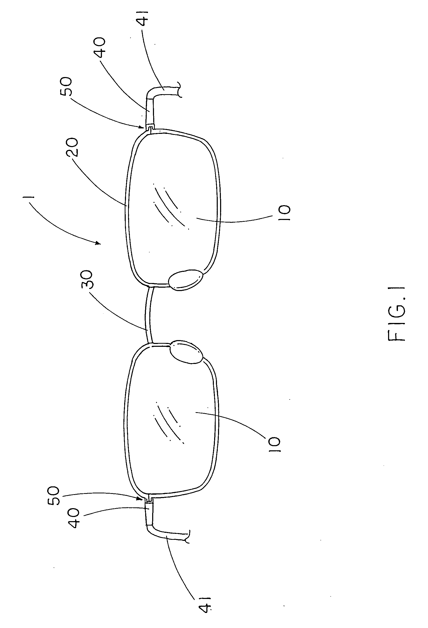
[0050] Referring to FIG. 1 to FIG. 2 of the drawings, a spectacle set according to the present invention is illustrated, wherein the spectacle set comprises at least a decorative frame 1 for supporting two lenses 10 in position.

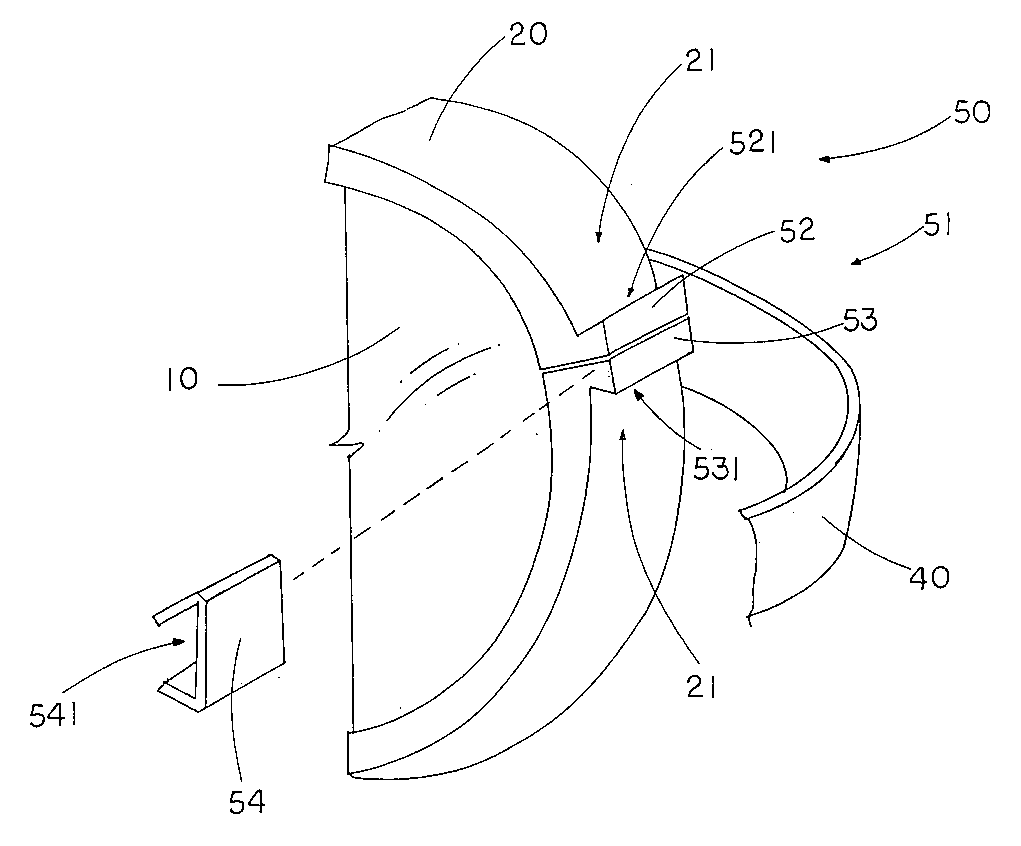
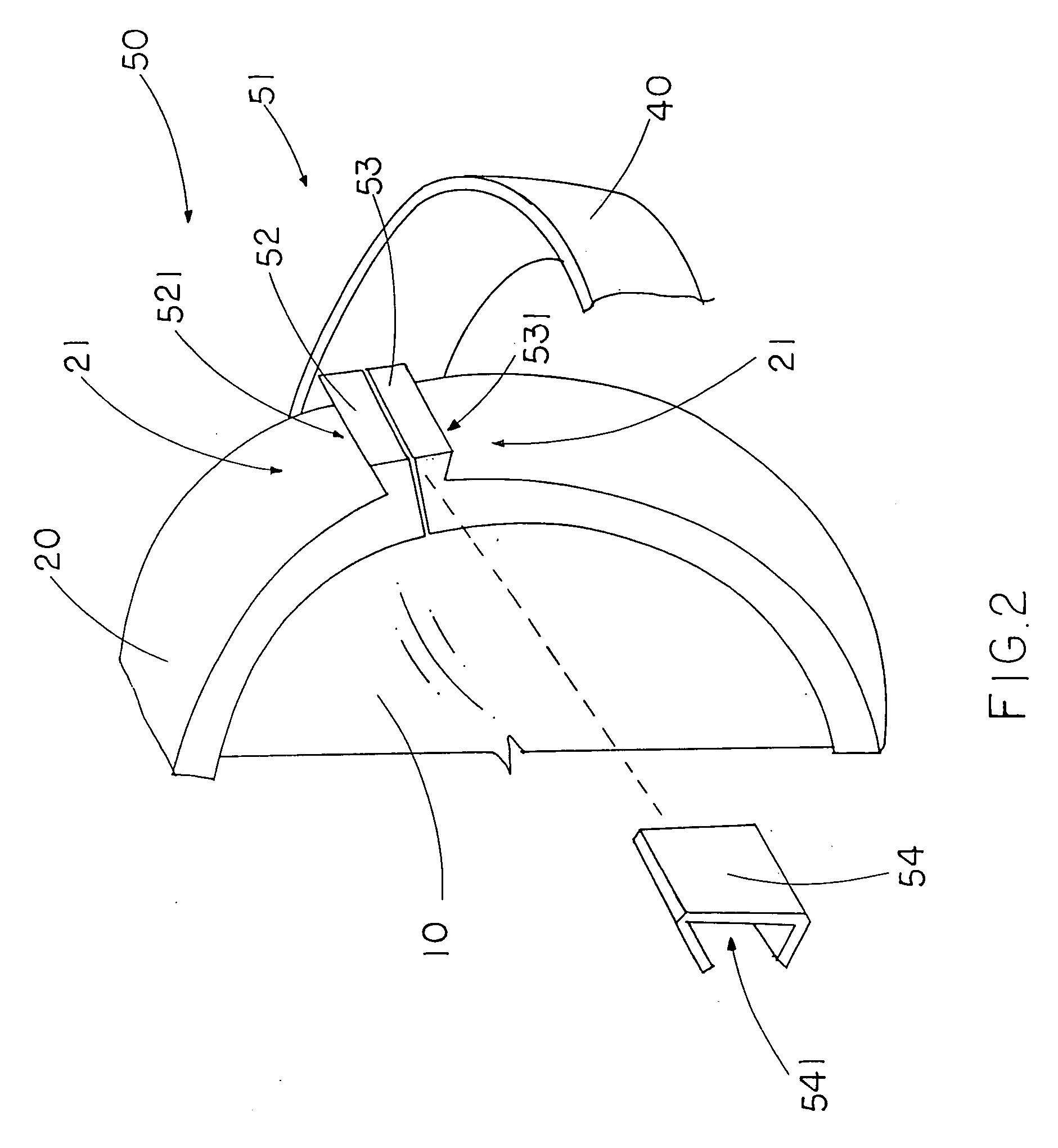
[0051] The decorative frame 1 comprises two lens rims 20, a bridge 30 extended between two inner sides of the lens rims 20, two side extensions 40 provided at two outer sides of the lens rims 20 for coupling a pair of temples 41 respectively, and a free-hand securing device 50 detachably mounting the two lenses 10 on the lens rims 20 respectively in a toolless manner.

[0052] According to the first embodiment, each of the lens rims 20 is shaped and sized corresponding to the lens 10 wherein each of the lens rims 20 having a C-shape has two free ends 21 arranged in such a manner that when the two free ends 21 are aligned with each other, the lens rim 20 form a circular structure to encircle a peripheral edge of the respective lens 10. The securing device 50 is ...

sixth embodiment

[0084] the slider locker 54F comprises a top platform 541F rotatably mounted on the upper locking body 52F and a bottom platform 542F defining a locking cavity 543F between the top and bottom platforms 541F, 542F wherein the slider locker 54F is rotatably slid to lock up the upper locking body 52F with the lower locking body 53F when the bottom platform 542F is slid to engage with the lower locking body 53F to receive the upper and lower locking bodies 52F, 53F within the locking cavity 543F, as shown in FIGS. 13A and 13B.

[0085] As shown in FIG. 13A, the upper locking body 52F has an upper protrusion portion 521F and the lower locking body 53F has a lower protrusion portion 531F shaped and sized corresponding to the upper protrusion portion 521F wherein the slider locker 54F is slid to receive the upper and lower protrusion portions 521F, 531F within the locking cavity 543F to lock up the upper locking body 52F with the lower locking body 53F.

[0086] The securing device 5OF further...


PUM


Abstract

A spectacles set includes a lens frame, a decorative frame and a lens engaging arrangement. The lens frame includes two lenses and a lens retention arrangement spacedly supporting the two lens in position. The decorative frame includes two lens rims defining two lens areas respectively, a bridge extending between two inner sides of the lens rims, and two side extensions extending at two outer sides of the lens rims. The lens engaging arrangement is provided at a rear side of the decorative frame to detachably engaging with the lens frame at a position that when the lens retention arrangement is detachably mounted at the rear side of the decorative frame in a hidden manner, the two lenses are alignedly positioned at two lens areas respectively so as to keep an aesthetic appearance of the decorative frame with the two lenses.

Description

CROSS REFERENCE OF RELATED APPLICATION [0001] This is a Continuation-In-Part application that claims the benefit of priority under 35U.S.C.§119 to a non-provisional application, application Ser. No. 11 / 004,112, filed Dec. 03, 2004.BACKGROUND OF THE PRESENT INVENTION [0002] 1. Field of Invention [0003] The present invention relates to spectacles, and more particularly to a spectacle set which comprises at least a decorative frame detachably mounting two lenses in position so as to allow the wearer to interchange the spectacle frame. [0004] 2. Description of Related Arts [0005] A conventional spectacle generally comprises two lenses and a spectacle frame for supporting the lenses in position, wherein the spectacle frame comprises two side extensions rearwardly extended from two outer sides of the lenses respectively for wearing onto the ears of the user, and a bridge extended between two inner sides of the lenses for supporting the lenses at a predetermined position above the user's n...

Claims


Application Information

Patent Timeline
Patent Type & Authority Applications(United States)
IPC IPC(8): G02C7/08
CPCG02C11/02G02C1/08G02C1/00G02C1/02G02C1/04G02C1/10G02C2200/08
Inventor LI, XIN LIANG
Owner LI XIN LIANG
Why Eureka
Try Eureka