Internal gear shaving machine

a shaving machine and gear technology, applied in the direction of gear teeth, gear manufacturing apparatus, manufacturing tools, etc., can solve the problems of difficult change of workpieces and engagement (phasing) of shaving cutters and internal gears, adversely affecting processing accuracy,

Active Publication Date: 2006-11-16
KANZAKI KOKYUKOKI MFG
View PDF2 Cites 22 Cited by
  • Summary
  • Abstract
  • Description
  • Claims
  • Application Information

AI Technical Summary

Benefits of technology

[0038] An internal gear shaving machine according to the present invention is an internal gear shaving machine in which a shaving cutter engages an internal gear held by a workpiece chuck at a crossed axes angle, and the tooth flanks of the internal gear are subjected to final machining while at least one of the shaving cutter and workpiece chuck is rotationally driven, the internal gear shaving machine being so constituted that the workpiece chuck and shaving cutter are supported movably toward and away from each other in a vertical orientation with the work chuck higher, and are supported movably in the horizontal direction relative to each other, and the workpiece chuck holds the outer circumferential surface of the internal gear so that the axis of rotation of the internal gear is oriented in an up-down direction and shavings produced during processing by the shaving cutter can fall downwardly from the internal gear.

Problems solved by technology

However, in such a known internal gear shaving machine, shavings produced during shaving disadvantageously remain on the internal teeth of the internal gear and adversely affect the processing accuracy.
Moreover, there is a problem of the difficulty in changing the workpiece and the engagement (phasing) of the shaving cutter and the internal gear in changing workpieces.

Method used


Image

  • Internal gear shaving machine
  • Internal gear shaving machine
  • Internal gear shaving machine

Examples


first embodiment

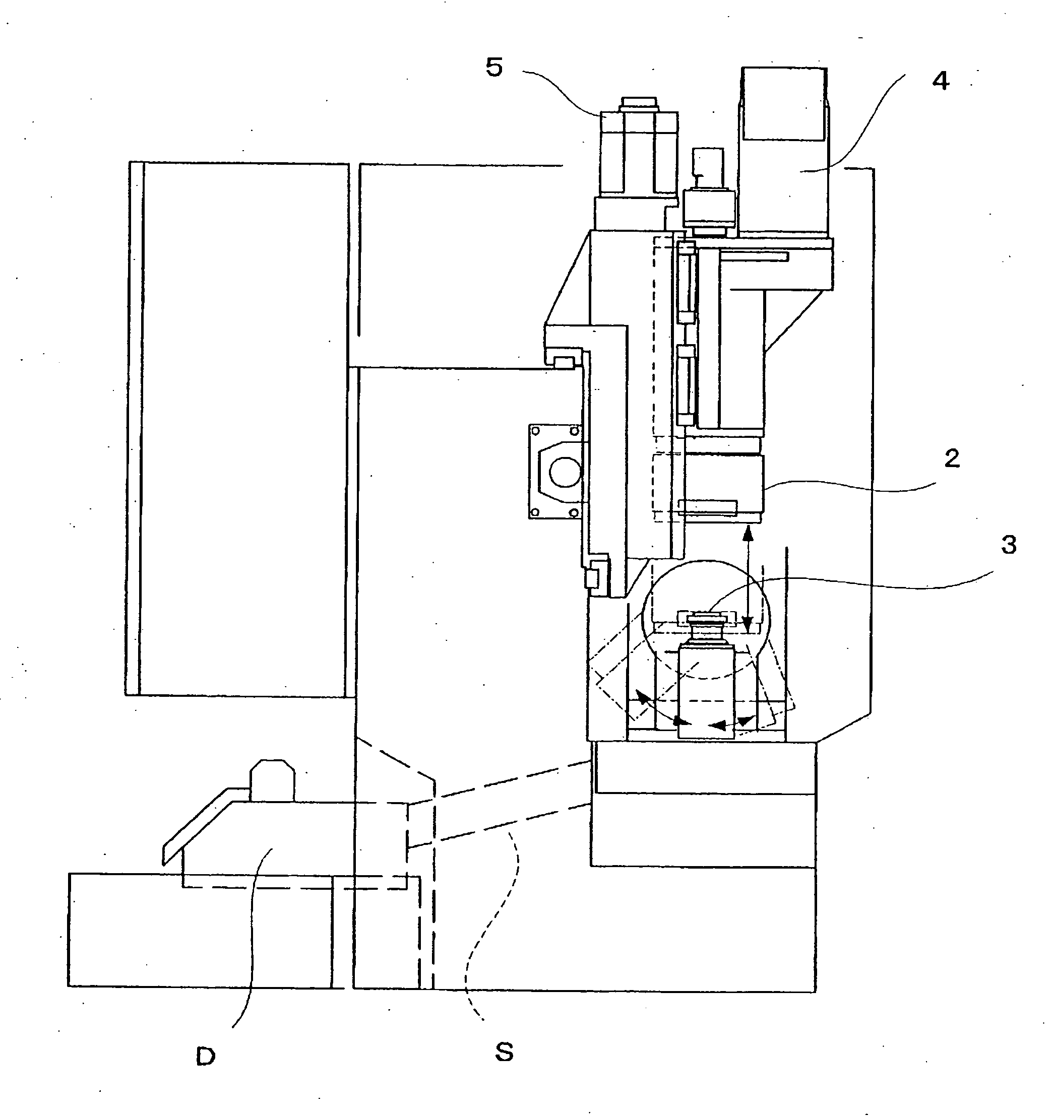
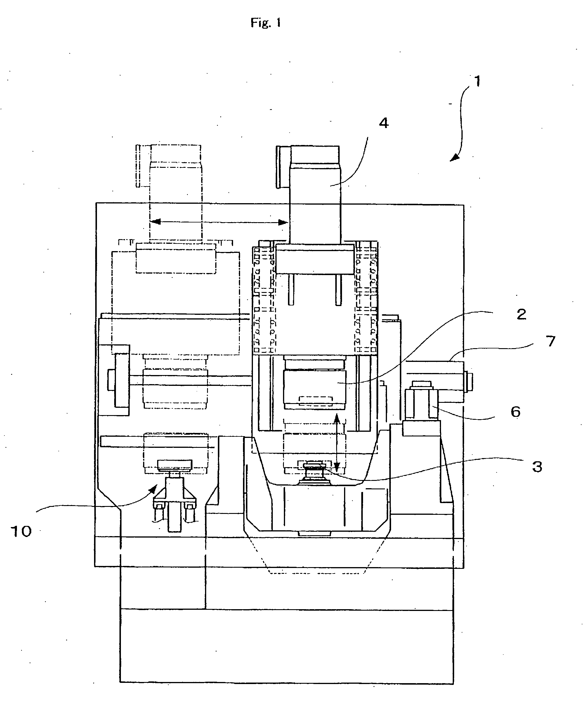
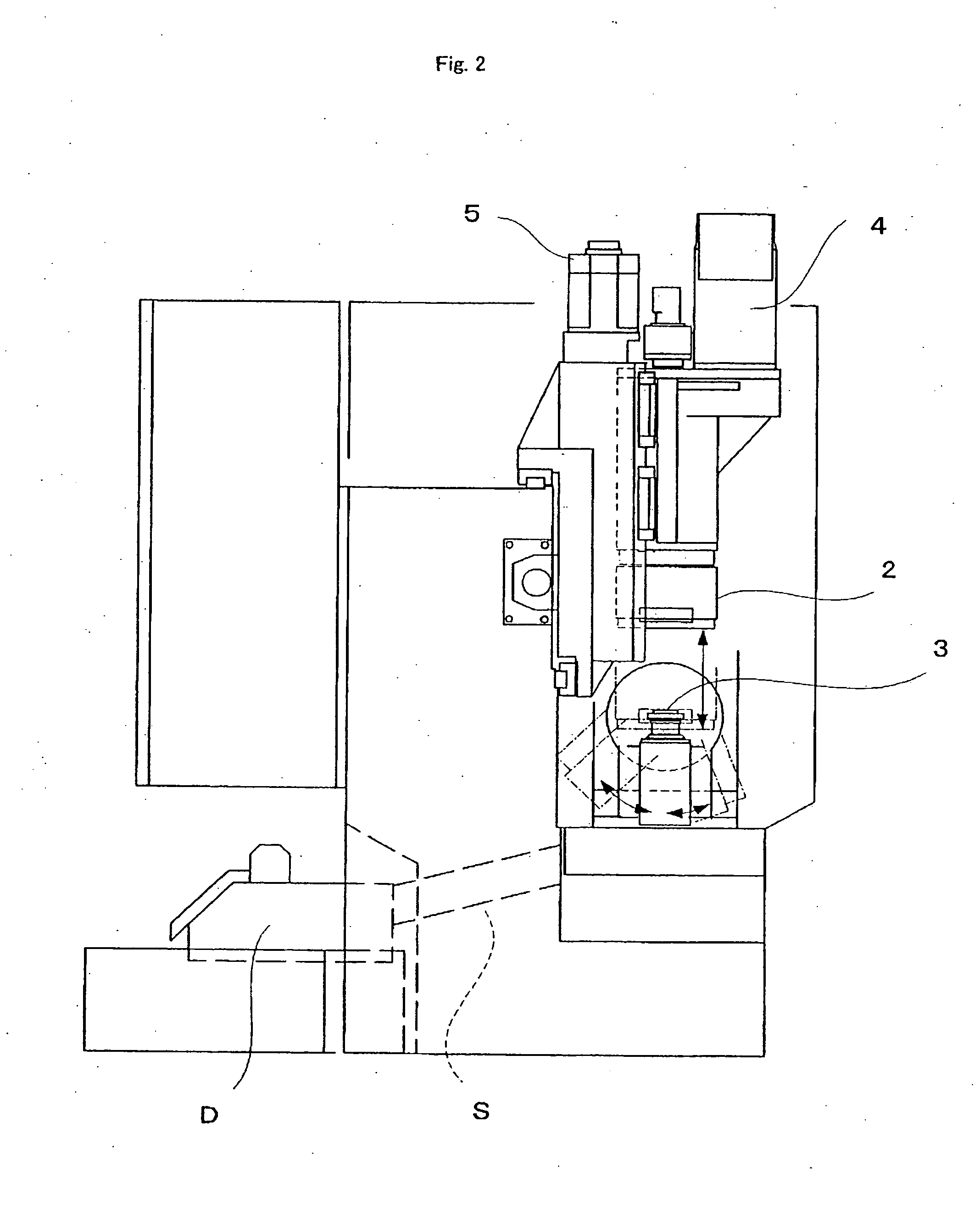
[0063] an internal gear shaving machine according to the present invention will be described below with reference to FIGS. 1 to 7. FIG. 1 shows a front view of the internal gear shaving machine; FIG. 2 shows a side elevation view; and FIG. 3 shows a plan view, respectively.

[0064] An internal gear shaving machine 1 comprises a workpiece chuck 2 that holds an internal gear as a workpiece to be subjected to a shaving process, and a shaving cutter 3 which conducts final machining in engagement with the internal gear.

[0065] The workpiece chuck 2 and shaving cutter 3 are disposed in a vertical orientation with the workpiece chuck 2 higher.

[0066] The workpiece chuck 2 can be rotationally driven by a spindle motor 4 about the vertical axis, and is supported movably in the vertical direction along with the spindle motor 4 by a lifting and lowering actuator 5. Further, the workpiece chuck 2 is supported laterally and horizontally movably, and is driven by an actuator 7.

[0067] The workpiece...

second embodiment

[0095] The workpiece carrying member of the second embodiment has a workpiece loading arm 41 and a workpiece unloading arm 42.

[0096] The workpiece loading arm 41 is supported freely swingably around a first pivot axis 41a parallel to the axis of rotation of the workpiece chuck 2, and swings between a workpiece change position Yc positioned on the travel path of the workpiece chuck 2 in the vertical direction and a workpiece loading position Yin remote from this workpiece change position toward the right front.

[0097] The workpiece unloading arm 42 is supported freely swingably around a second pivot axis 42a parallel to the axis of rotation of the workpiece chuck 2, and swings between the workpiece change position Yc and a workpiece removing position Yout remote from the workpiece change position Yc toward the left front.

[0098] The workpiece loading arm 41 supports the internal gear with its axis of rotation oriented in the vertical direction so that the workpiece chuck 2 can hold t...

third embodiment

[0102] the internal gear shaving machine according to the present invention is described below with reference to FIGS. 14 to 28. It should be noted that FIGS. 14 to 16 correspond to FIGS. 1 to 3.

[0103] Although not illustrated in the first and second embodiments, the entire front face and side face of the entire apparatus are covered with a body cover 70 as shown in FIGS. 1 to 3 with chain lines. Numeral 70a in FIGS. 1 to 3 represents an opening and closing viewing window in the body cover 70.

[0104] The internal gear shaving machine comprises a cutter positioning mechanism for stopping a shaving cutter 3 at a predetermined rotation angle position about its spindle shaft. The cutter positioning mechanism can comprise, for example, as shown in FIG. 18, a latching recess 3c formed on a spindle shaft 3s of the shaving cutter 3, and a phasing pin 3p which operates engageably and disengageably with the latching recess 3c by an air cylinder 3d. Moreover, a projection 3g is formed on the s...


PUM

PropertyMeasurementUnit
angleaaaaaaaaaa
angleaaaaaaaaaa
angleaaaaaaaaaa

Abstract

An internal gear shaving machine 1 which brings a shaving cutter 3 and an internal gear held by a workpiece chuck 2 into engagement with a crossed axes angle, and subjects the tooth flanks of the internal gear to final machining while it rotationally drives at least one of the shaving cutter 3 and the workpiece chuck 2. The workpiece chuck 2 and shaving cutter 3 are supported movably toward and away from each other in a vertical direction with the workpiece chuck 2 higher and supported movably in the horizontal direction relative to each other. The workpiece chuck 3 is constituted to hold the outer circumferential surface of the internal gear with the axis of rotation of the internal gear oriented in a up-down direction so that shavings produced during processing by the shaving cutter can fall downwardly from the internal gear.

Description

TECHNICAL FIELD [0001] The present invention relates to an internal gear shaving machine finished by cutting an internal gear with a shaving cutter. BACKGROUND ART [0002] In known general internal gear shaving machines as disclosed in, for example, Japanese Unexamined Patent Publication No. 2003-117729, an internal gear rotatably supported around a horizontal axis by a workpiece chuck engages a shaving cutter at a predetermined crossed axes angle, and the tooth flanks of the internal gear are finished while at least one of the shaving cutter and the workpiece chuck is rotationally driven. [0003] However, in such a known internal gear shaving machine, shavings produced during shaving disadvantageously remain on the internal teeth of the internal gear and adversely affect the processing accuracy. Moreover, there is a problem of the difficulty in changing the workpiece and the engagement (phasing) of the shaving cutter and the internal gear in changing workpieces.BRIEF DESCRIPTION OF T...

Claims


Application Information

Patent Timeline
Patent Type & Authority Applications(United States)
IPC IPC(8): B23F1/00
CPCB23F19/06B23F23/04B23F23/06Y10T409/100954Y10T409/107632Y10T409/109699Y10T409/10954Y10T409/105565Y10T409/100795Y10T409/105724
Inventor TAKI, HIROKIYOSHIDA, RYOJIYAMAGUCHI, MASAAKI
Owner KANZAKI KOKYUKOKI MFG
Why Eureka
Try Eureka