Analyte sensing biointerface

Active Publication Date: 2006-11-16
DEXCOM
View PDF99 Cites 115 Cited by
  • Summary
  • Abstract
  • Description
  • Claims
  • Application Information

AI Technical Summary

Benefits of technology

[0006] Devices and methods are needed that address the FBR's negative effects on biosensing. The devices and methods of

Problems solved by technology

One difficulty encountered with implantable biosensors, such as implantable glucose sensors, is that many of these devices tend to lose their function with time after implantation.

Method used


Image

  • Analyte sensing biointerface
  • Analyte sensing biointerface
  • Analyte sensing biointerface

Examples


Embodiment Construction

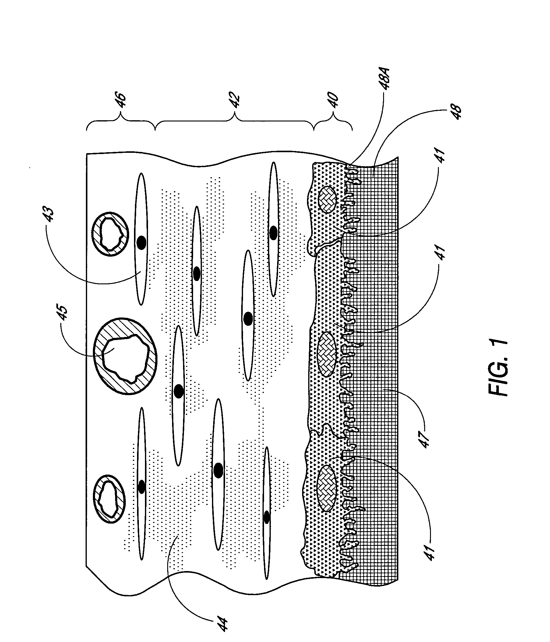
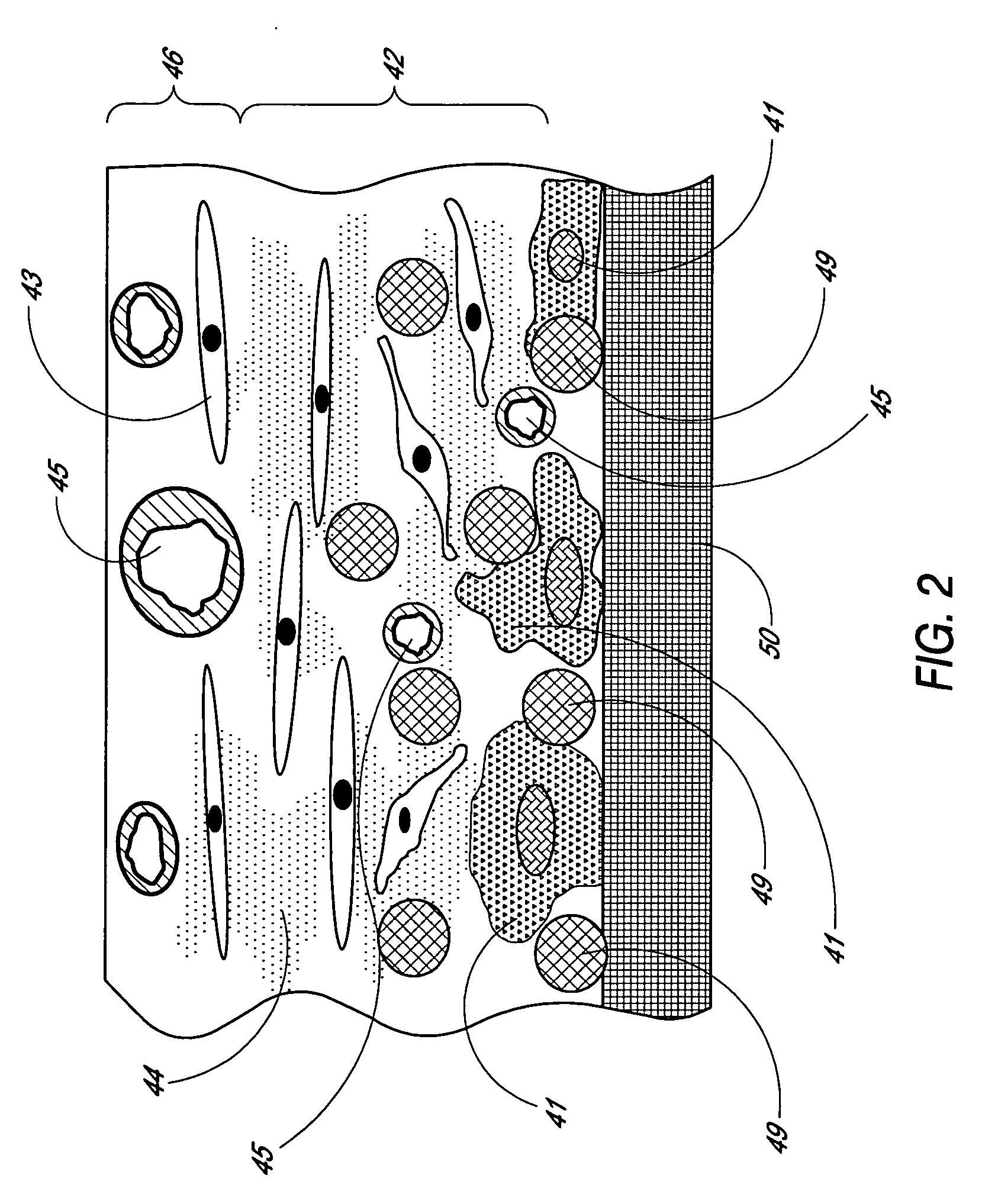
[0092] Described herein are structures for use in implantable analyte sensors. The term “analyte” as used herein is a broad term, and is to be given its ordinary and customary meaning to a person of ordinary skill in the art (and is not to be limited to a special or customized meaning),.and refers without limitation to a substance or chemical constituent in a biological fluid (e.g., blood, urine, extracellular fluid) that is intended to be analyzed. In one embodiment, the analyte is blood glucose. The term “detection” of an analyte as used herein is a broad term, and is to be given its ordinary and customary meaning to a person of ordinary skill in the art (and is not to be limited to a special or customized meaning), and refers without limitation to detecting the presence of an analyte and / or detecting the amount of an analyte present. In one embodiment, detection of an analyte provides a measure of the concentration of the analyte in a biological fluid.

[0093] One method of addres...


PUM


Abstract

Disclosed herein is an analyte sensing biointerface that comprises a sensing electrode incorporated within a non-conductive matrix comprising a plurality of passageways extending through the matrix to the sensing electrode. Also disclosed herein are methods of manufacturing a sensing biointerface and methods of detecting an analyte within tissue of a host using an analyte sensing biointerface.

Description

RELATED APPLICATION [0001] This application claims the benefit of U.S. Provisional Application No. 60 / 671,622, filed Apr. 15, 2005, and U.S. Provisional Application No. 60 / 683,923, filed May 23, 2005, both of which are incorporated herein by reference in their entirety.FIELD OF THE INVENTION [0002] The present invention relates to the field of biosensing. More particularly, the present invention relates to analyte sensors for implantation into a host. BACKGROUND OF THE INVENTION [0003] Biosensors are devices that can be used to detect the presence or amount of analytes, such as biomolecules, in a biological sample. Some biosensors are designed to detect analytes in a living host. Such detection can advantageously be done through the use of implantable biosensors, which are implanted intravascularly or within tissue to detect the presence or amount of analyte at the implantation location. One practical application of implantable biosensors is implantable glucose sensors that continuo...

Claims


Application Information

Patent Timeline
IPC IPC(8): C12M1/34
CPCA61B5/0031A61B5/14532A61B5/1486C12Q1/001C12Q1/006A61B5/14865B33Y80/00
Inventor SIMPSON, PETER C.BRAUKER, JAMES H.
Owner DEXCOM
Why Eureka
Try Eureka