High-frequency measuring system having spatially separated high-frequency modules

Active Publication Date: 2006-11-16
ROHDE & SCHWARZ GMBH & CO KG
View PDF9 Cites 16 Cited by
  • Summary
  • Abstract
  • Description
  • Claims
  • Application Information

AI Technical Summary

Benefits of technology

[0015] According to another aspect, a high-frequency module can be fitted with a separate power supply, so that high-frequency modules, which have a high DC power requirement, for example, high-frequency modules with a considerable transmission power, can also be used. The separate power supply, which is either integrated in the housing of the high-frequency module or arranged externally, therefore renders unnecessary a supply of DC power via the measuring-device unit and the connecting line.
[0016] Moreover, in one embodiment, an optimum adaptation to the respective measuring task can be achieved by providing several digital interfaces on the measuring-device unit, which are formed, for example, both as serial interfaces and also as parallel interfaces, wherein the interfaces can especially be formed either as optical interfaces or electrical interfaces. In particular, these interfaces can be adapted to the re

Problems solved by technology

Complex corrective calculation methods can reduce these effects in the determination of the true measured values, but can never completely eliminate them.
A further difficulty is that the high-frequency properties of a cable can change over time, for example as a result of mechanical stress.
On the one hand, the attenuation of the cable means that the measuring device must generate a higher level than is required directly in the device under test, which, especially in the case of high-frequencies, makes the measuring devices more expensive.
Weak signals transmitted from the device under test may fall below the detection threshold of the measuring device as a result of the cable attenuation, so that, under some circumstances, more expensive, sensitive measuring devices are required.
With an increasing length of cable, not only are these effects intensified, but the risk is also increased that interference signals (for example, from the base stations disposed in the proximity of the building, in wh

Method used


Image

  • High-frequency measuring system having spatially separated high-frequency modules
  • High-frequency measuring system having spatially separated high-frequency modules
  • High-frequency measuring system having spatially separated high-frequency modules

Examples


Example

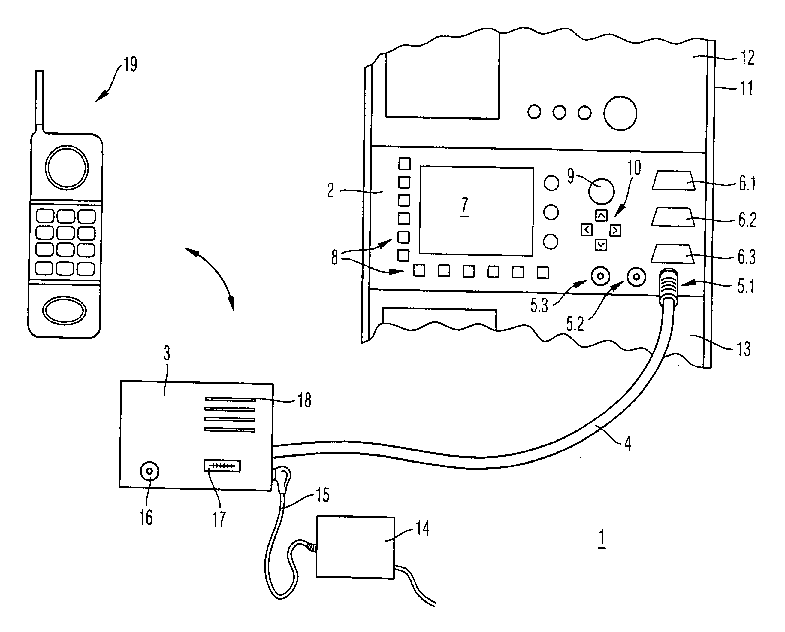
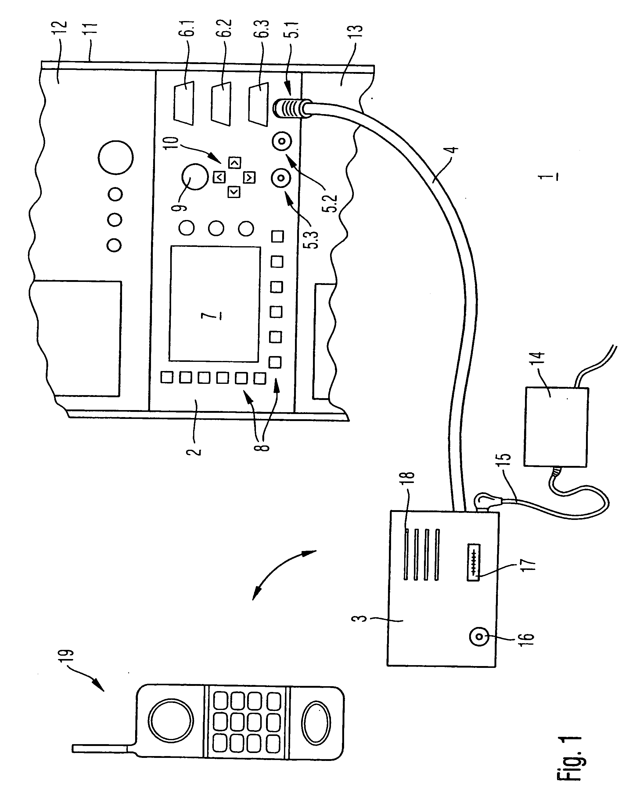
[0022] A measuring system 1 consistent with the invention, as illustrated in FIG. 1, comprises a measuring-device unit 2, which is connected, in the exemplary embodiment shown, to only one high-frequency module 3. The high-frequency module 3 is connected to the measuring-device unit 2 via a connecting cable 4, the high-frequency module 3 being connected to a first socket 5.1 by means of the connecting cable 4. A second socket 5.2 and a third socket 5.3, which are identical, for example in their structure, to the first socket 5.1, are provided on the measuring-device unit 2.

[0023] In the illustrated exemplary embodiment, the measuring-device unit 2 provides three further connecting options 6.1, 6.2 and 6.3 for high-frequency modules, thereby providing, for example, an alternative connecting option to the three sockets 5.1, 5.2 and 5.3. For instance, the three sockets 5.1, 5.2 and 5.3 can form a serial, optical interface, while the three connecting options 6.1 to 6.3 can realize a pa...


PUM


Abstract

A high-frequency measuring system is provided for measuring a test device with a measuring device unit and at least one high-frequency module connected to the measuring device unit. Each high-frequency module is located spatially separated from the measuring device unit and is connected to the measuring device unit via a digital interface.

Description

FIELD OF THE INVENTION [0001] The invention relates to a measuring system for high-frequency communications systems. BACKGROUND OF THE INVENTION [0002] In the development and production of devices for high-frequency communications systems, such as digital mobile telephone or WLAN (wireless local area network), it is desirable to check the performance of the relevant devices or component groups with regard to data transmission or message transmission. Measuring instruments connected directly by means of a cable to the antenna port of the device under test (DUT) are generally used for this purpose. If the device under test has only a permanently-installed internal antenna, an antenna coupler, which establishes the connection with the antenna of the device under test by electromagnetic coupling, is inserted between the device under test and the end of the cable. [0003] The high-frequency signals to be transmitted or respectively received are passed along the cable. In order to test a m...

Claims


Application Information

Patent Timeline
IPC IPC(8): H04B17/00G01R23/00
CPCG01R23/00
Inventor STEFFEN, ROLANDPLAUMANN, RALF
Owner ROHDE & SCHWARZ GMBH & CO KG
Why Eureka
Try Eureka