Removable fletching for use with archery arrows
- Summary
- Abstract
- Description
- Claims
- Application Information
AI Technical Summary
Benefits of technology
Problems solved by technology
Method used
Image

Examples
third embodiment
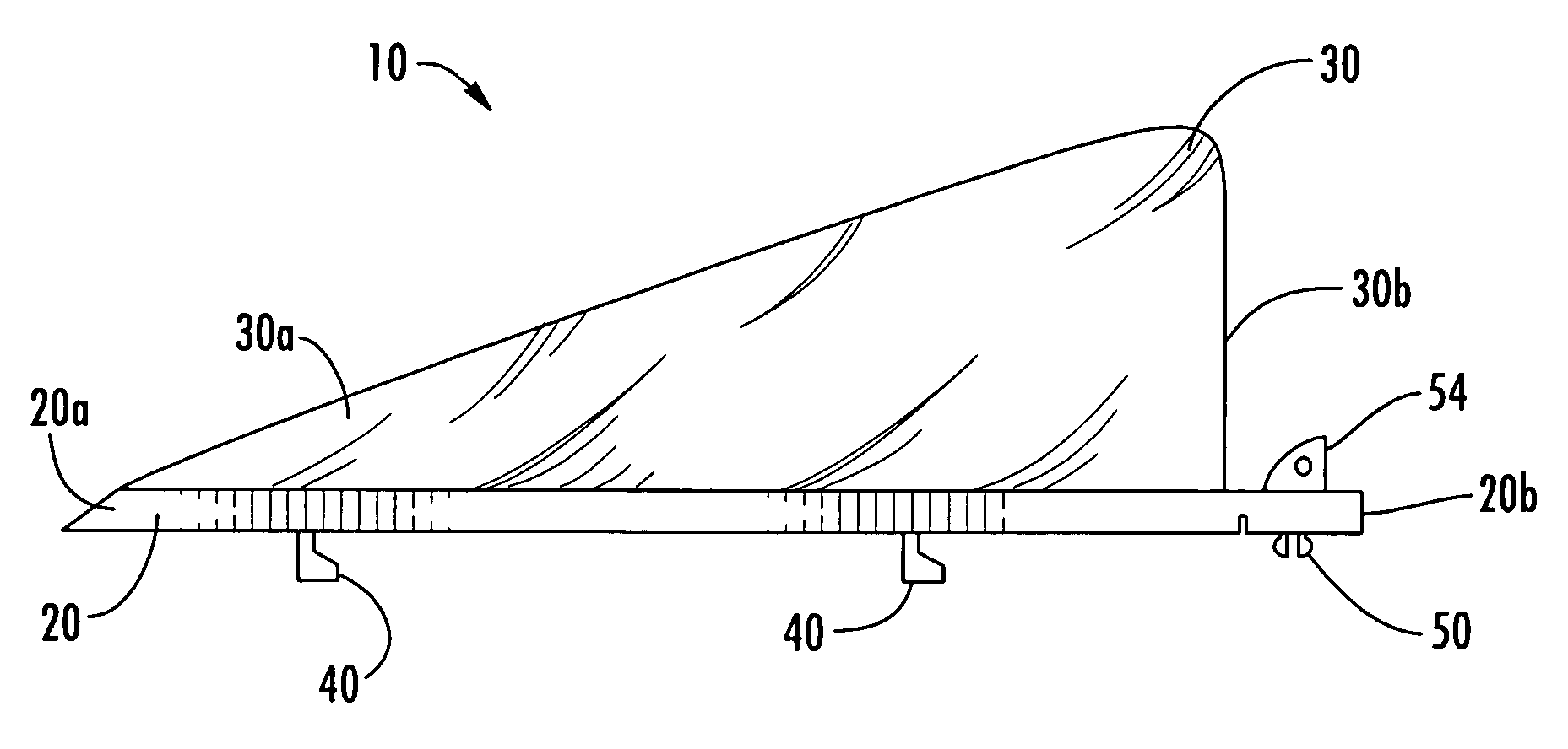
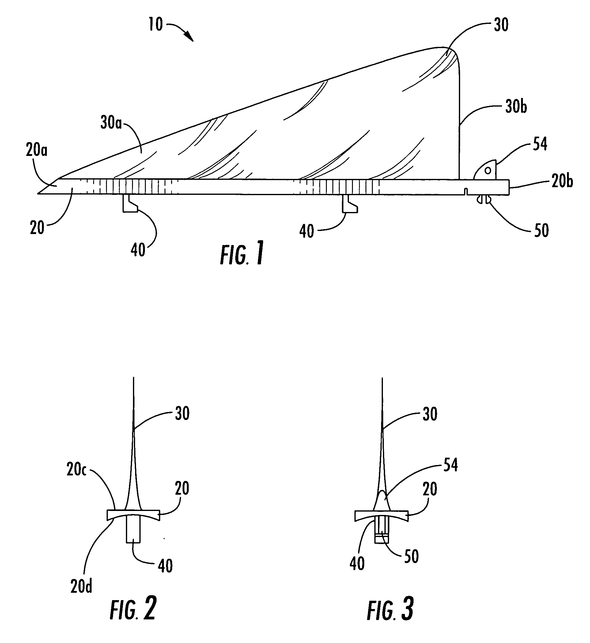
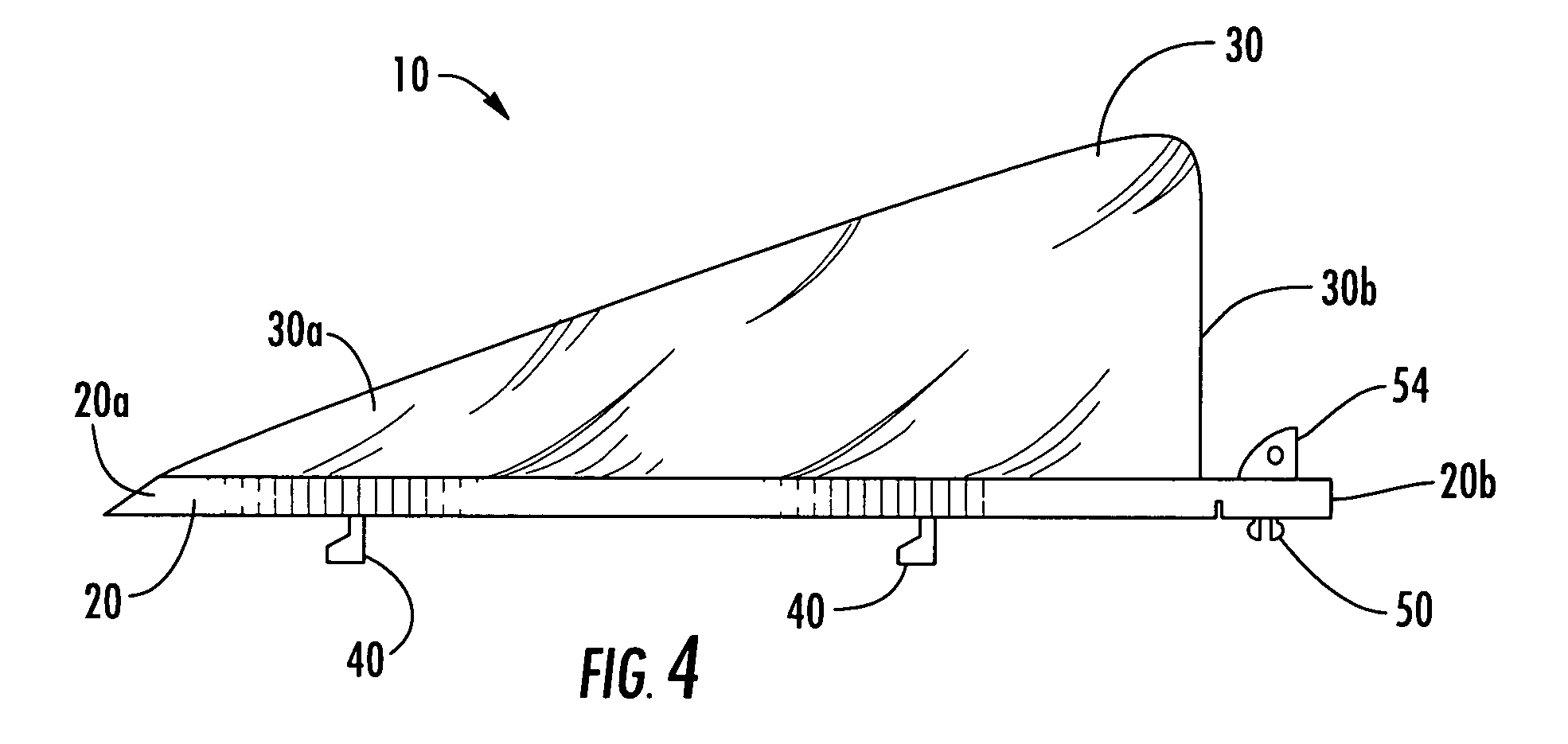
[0036] Still referring to FIG. 11, in accordance with the invention, a method for installing the invented fletch is illustrated. As shown, an arrow body 100 has been pre-drilled with holes corresponding to the locating pins 140 and the locking pin 150. To install the fletch 10 within the arrow body 100, the locating pins 40 are inserted into the corresponding locating pin holes 140. The fletch is then pulled rearward with respect to the arrow body 100. As the fletch is pulled rearward, the angled engagement surfaces of the locating pins 40 draw the fletch towards the center of the arrow body until the lower 20d surface of the mounting body 20 is in firm frictional contact with the outer surface of the arrow body and the engagement surface of the locating pins 40 is in firm frictional contact with the inner surface of the arrow body 100. Once the fletch is pulled rearward with respect to the arrow body 100, the locking pin 50 is located over locking pin hole 150 and may be snap fit w...
fourth embodiment
[0038] According to the invention, a fletch replacement kit is provided, comprising at least one fletch as described above and a drill jig. Referring to FIG. 12, the contemplated drill jig 200 is an elongate member having a central bore 210 defined through the jig, at least one locating pin guide hole 240 defined through a portion of the jig perpendicular to the central bore, and at least one locking pin guide hole 250 defined through a portion of the jig perpendicular to the central bore. Holes may be easily drilled within an arrow body corresponding to the locating and locking pins of the fletch by inserting the arrow body through the central bore 210 and drilling holes through the arrow wall as directed by the locating and locking pin guide holes 240,250. The guide holes of the jig may be positioned such that their centers define a line parallel to the center line of the central bore 210. Alternatively, the guide holes may be offset with respect to the central bore 210 as shown i...
PUM
 Abstract
Description
Claims
Application Information