Eureka AIR delivers breakthrough ideas for toughest innovation challenges, trusted by R&D personnel around the world.

Safety padlock

Inactive Publication Date: 2006-11-23
R D Y INSTALLATION COMMERCE 2000
View PDF25 Cites 3 Cited by
  • Summary
  • Abstract
  • Description
  • Claims
  • Application Information

AI Technical Summary

Benefits of technology

[0022] It is an object of the present invention to provide a padlock wherein the hasp is retained with the padlock body in all phases of its operation and which is not exposed when in the locked position.

Problems solved by technology

The hasp is looped through an object to be secured but because of the exposed nature of the hasp, both the hasp and the secured object are vulnerable to abuse.
Each of these steps add significantly to the cost of the padlock.
Another defense is the provision of a shield or shroud for the shackle to make access of cutting or forcing tools to the shackle and hasp staple difficult, but this defense is often costly and / or awkward to implement.
Furthermore, the latching mechanisms and shackles are often vulnerable to wedging, prying, and torsional attack because of the excessive space provided by the typical U shaped shackle and the sloppy fit with the hasp staple or attachment device which is often a characteristic of this arrangement.
In addition, the mechanical operation of lifting and pivoting the U shaped shackle is sometimes subject to malfunction caused by the environmental effects of corrosion or foreign matter (dirt and grit) within the close fitting assembly with the padlock body needed for security.
Burglary, aimed at the theft of property from both commercial and private premises, whether these be movable road vehicles such as trucks, vans, recreational vehicles, trailers, and the like, or stationary structures such as stores, warehouses, garages, barns, and the like, is an ever growing problem in our society.
Frequently, it takes a professional thief less than a minute to overcome any of the currently available anti-theft devices, even if that requires sawing or cutting through the shackle or bolt of a padlock or the staple of a hasp.
The principal aim of these and other lock guard devices has been to make it more difficult and hence time-consuming for a burglar to gain access to the lock for the purpose of cutting either the bolt or shackle of the lock or the staple of an associated hasp with a bolt cutter or for sawing through such a shackle or staple with a hacksaw.
A so-protected structure will thus be a relatively limited interest to a prospective burglar or thief because of the higher degree of difficulty he or she will face to gain entrance to the protected premises in the shortest possible time and the least amount of noise.
This leads to the possibility of the hasp being lost.

Method used


Image

  • Safety padlock
  • Safety padlock
  • Safety padlock

Examples


Embodiment Construction

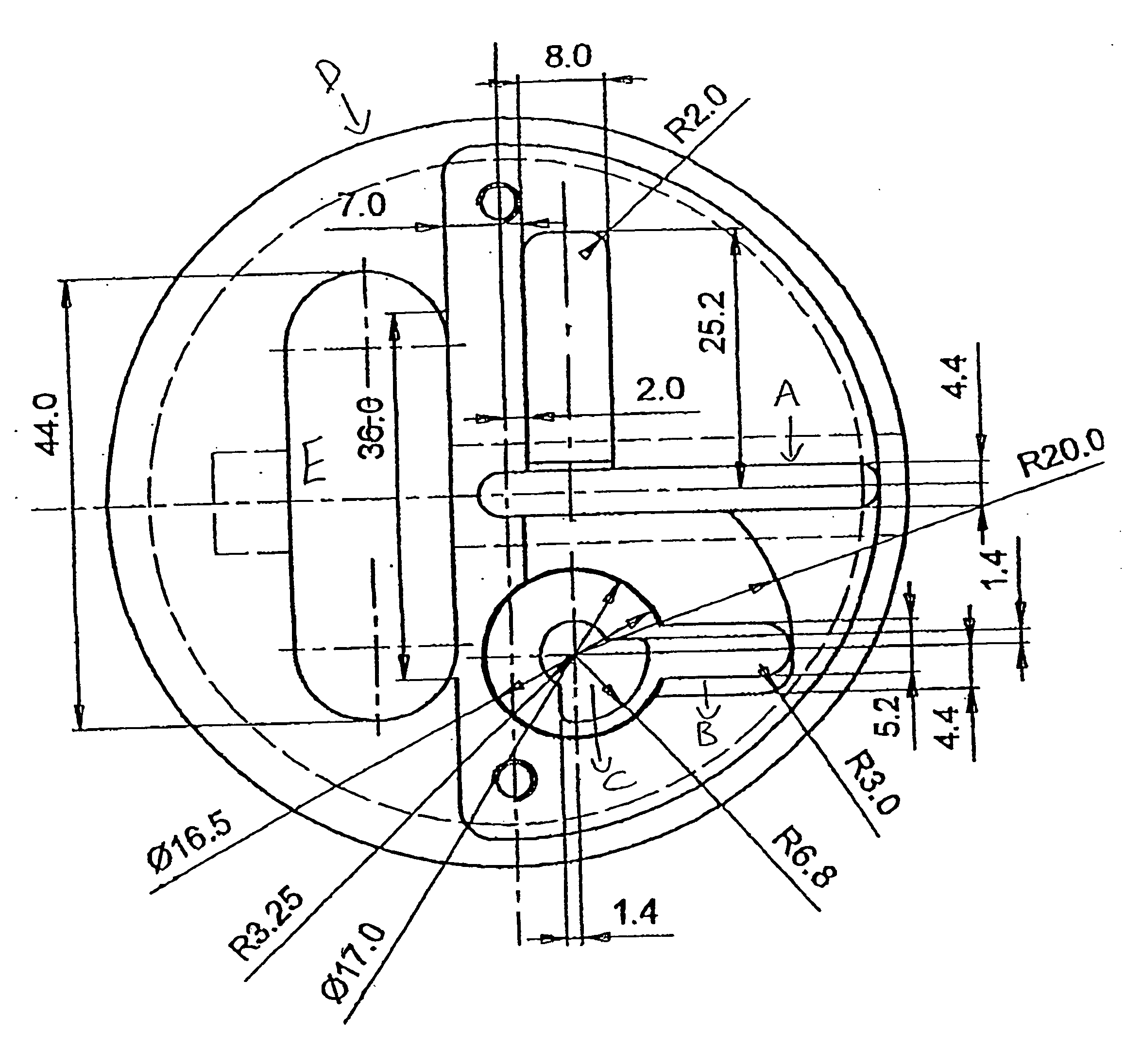
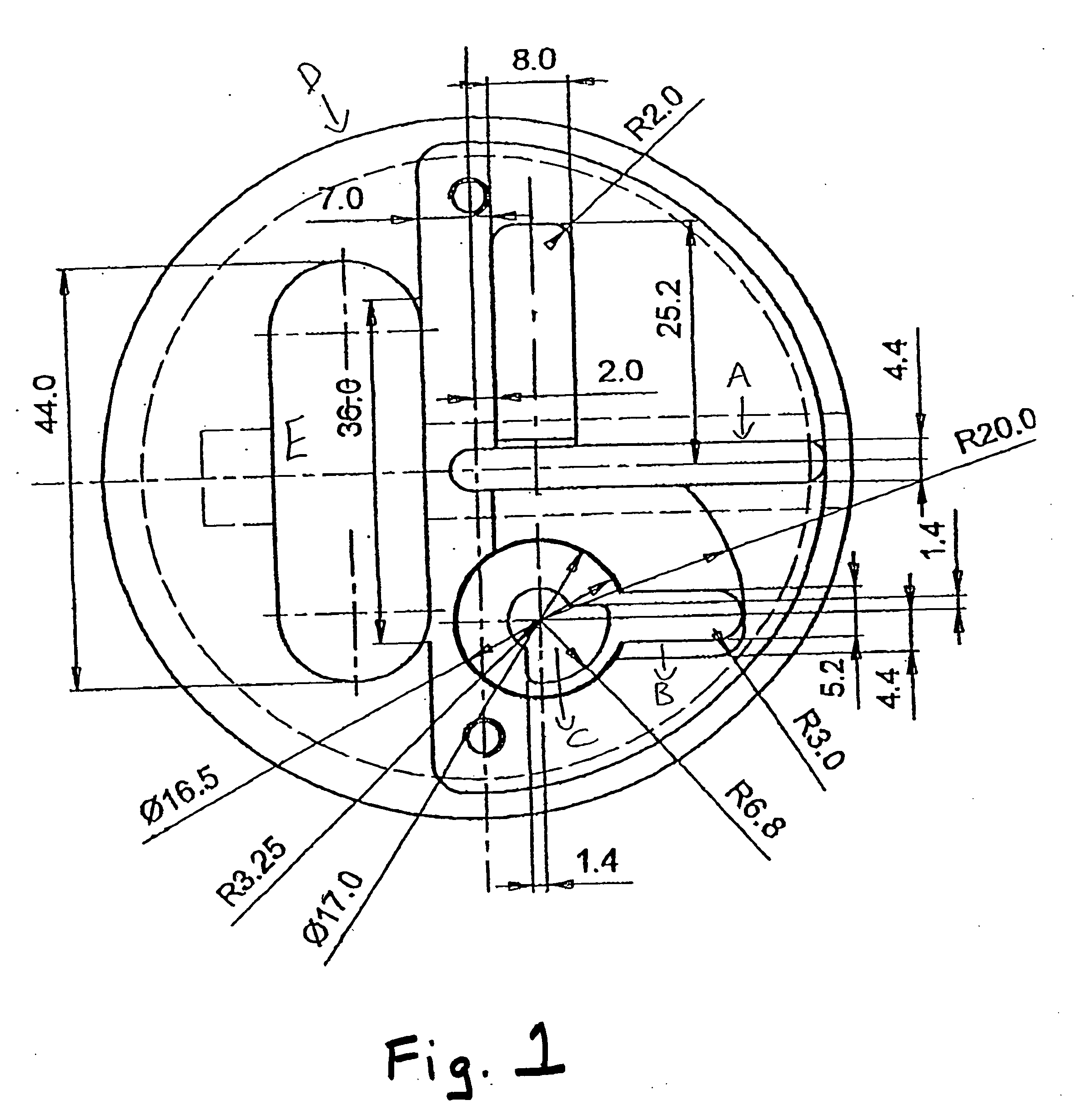
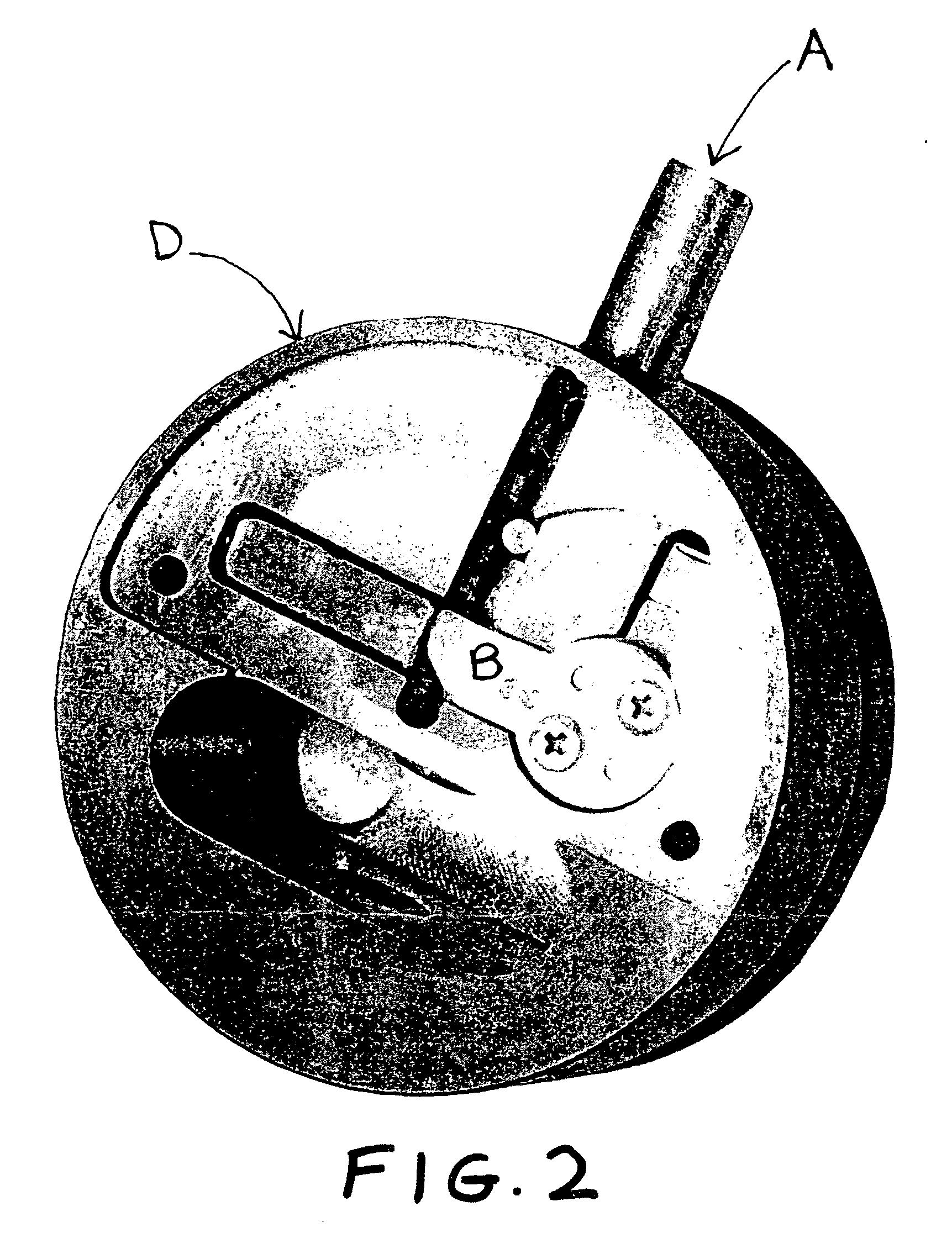
[0029] The padlock of the present invention includes a frame having a base on which a shackle slides. The slideable shackle includes a main body that extends into a toe portion. The toe portion of the shackle includes tapered sidewalls that are separated by a distance that gradually decreases toward the distal end of the toe.

[0030] The padlock includes means for maintaining the sliding bolt in a locked position and the entire padlock may be housed in a casing to hide at least the staple of the hasp.

[0031] The invention includes fastening means, which is adapted to be removeably connected to a doorjamb and to cooperate with a sliding shackle padlock, in place of a hasp device, to secure a door from unauthorized intrusion.

[0032] The lock has a flat-faced cylindrical housing and an internal key cylinder-operable bolt, which can be selectively protracted through a hasp staple or the like inside a channel in the housing, which intersects the path or movement of the bolt.

[0033] In use...


PUM


Abstract

The present invention provides a padlock comprising a padlock body having formed therein a slot arranged to receive an object to be secured, a hasp mounted in the body and arranged to be moved between a first, inoperative position in which the slot can receive an object to be secured and a second, operative position in which it is disposed across the slot, said hasp being retained in said body in all phases of its operation and, when in the operative position, extending across the slot within the confines of the body so that the portion of the hasp securing the object is shrouded.

Description

BACKGROUND OF THE INVENTION [0001] Presently available padlocks typically comprise a hasp which, when in the locked position is exposed. The hasp is looped through an object to be secured but because of the exposed nature of the hasp, both the hasp and the secured object are vulnerable to abuse. This invention relates to conventional shackle padlocks, specifically to an improved two piece shackle mechanism for padlocks. [0002] Historically padlocks using U shaped shackles have been found to be the most popular because of the ease and convenience of their attachment to and fit with the hasps and attachment to and fit with the hasps and attachment devices with which they are used, to prevent the opening, unlatching, or coming apart of the secured elements. [0003] The ubiquitous design, so popular for the last seventy or eighty years typically embodies a U shaped wire form that provides for the latching and locking of the shackle in the body of the padlock, and when unlocked and unlatc...

Claims


Application Information

Patent Timeline
IPC IPC(8): E05B67/36
CPCE05B67/36Y10T70/441
Inventor REITCHUK, DORON
Owner R D Y INSTALLATION COMMERCE 2000
Why Eureka
Eureka Blog
Learn More