
Window handle

a technology for window actuators and handles, applied in the direction of wing knobs, mechanical control devices, controlling members, etc., can solve the problems of complex and complicated conventional mechanisms that attach window handles to window actuators, and/or conventional mechanisms that facilitate the folding of window handles, etc., to achieve the effect of convenient and secure mounting

Inactive Publication Date: 2006-11-23
ARMADA TOOLWORKS
View PDF28 Cites 10 Cited by
  • Summary
  • Abstract
  • Description
  • Claims
  • Application Information

AI Technical Summary

Benefits of technology

[0007] Accordingly, one aspect of one or more embodiments of this invention provides a folding window handle that can easily and securely be mounted to a window actuator.
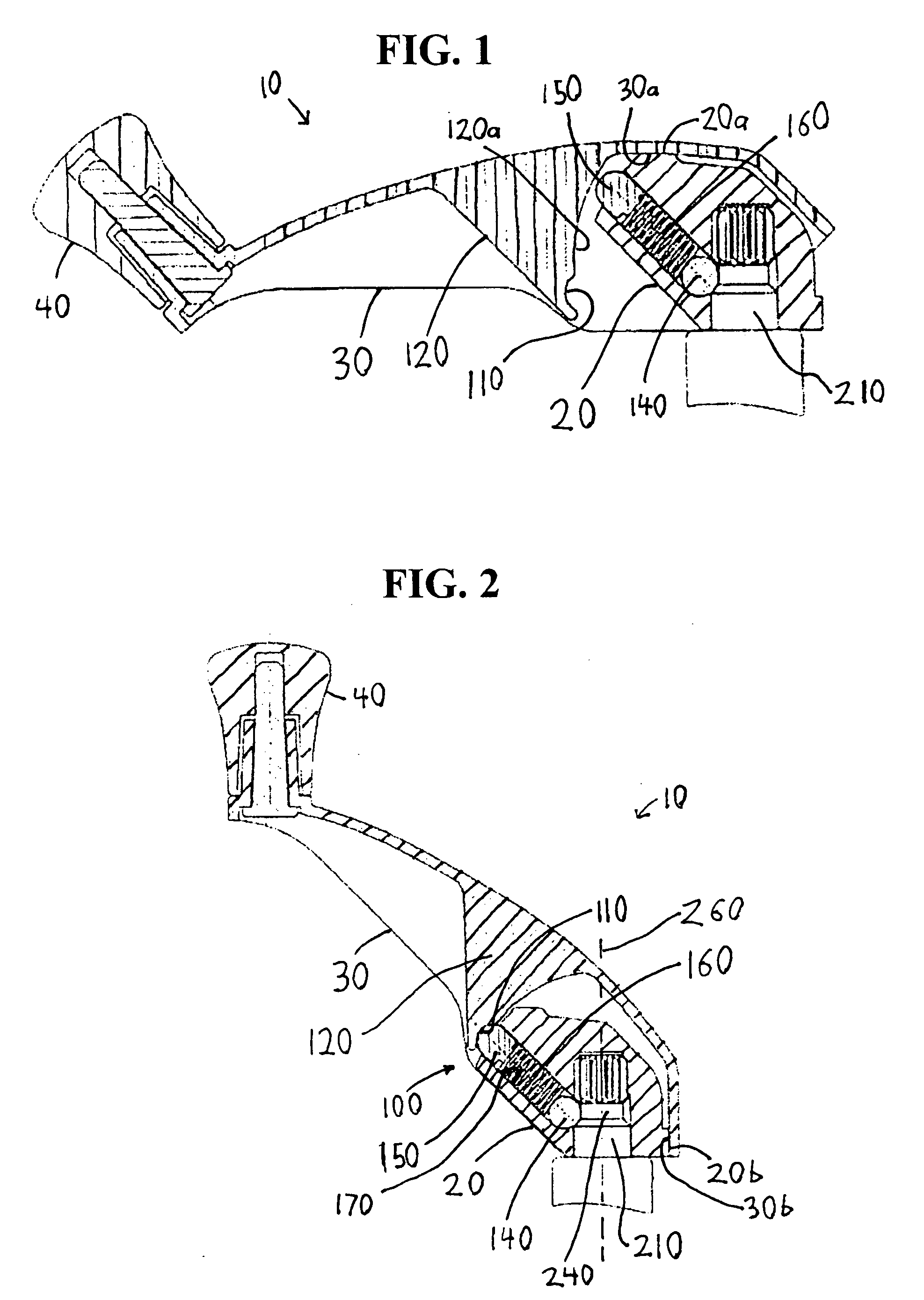
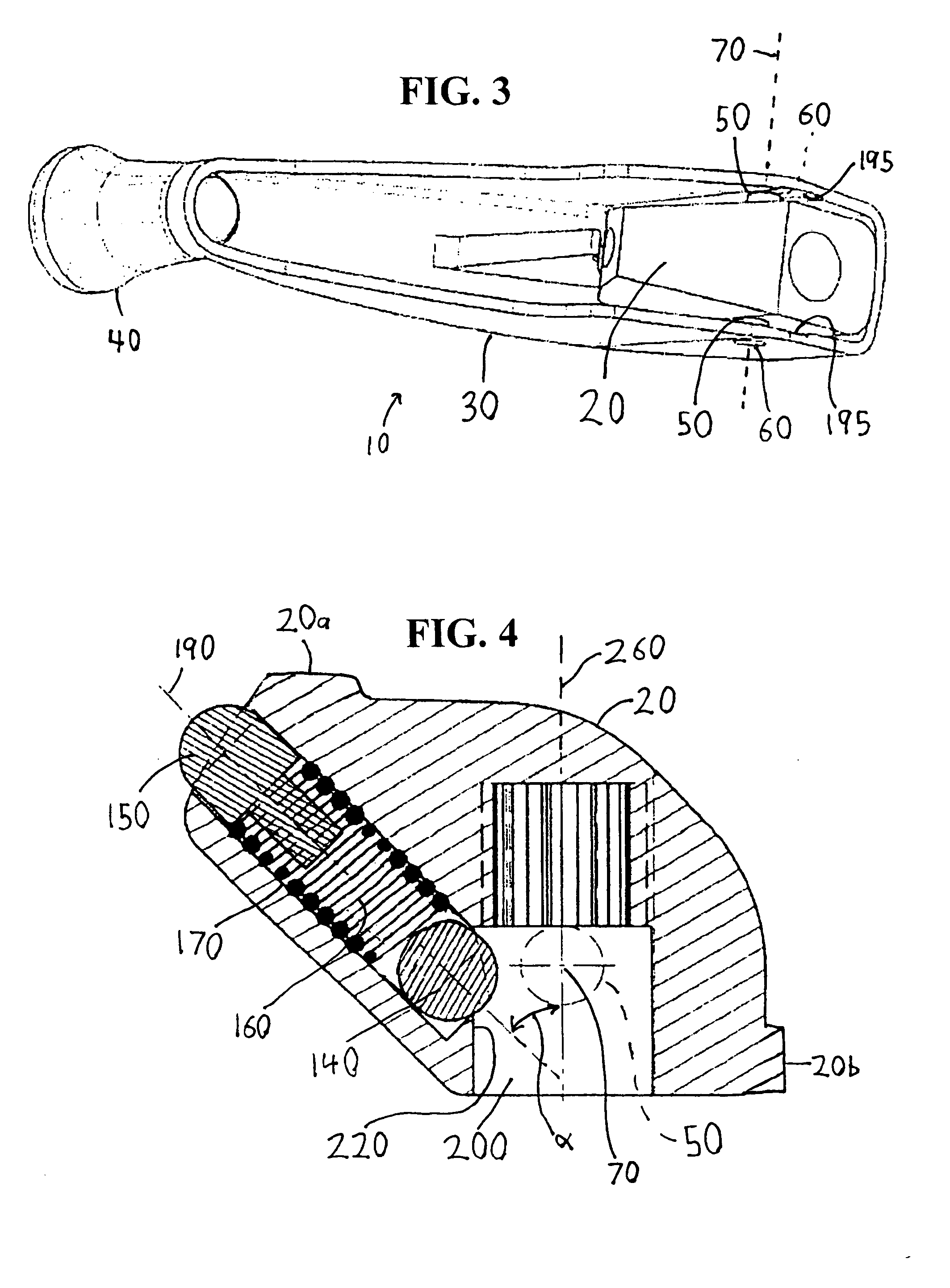
[0011] According to a further aspect of one or more of these embodiments, a second bore is disposed in the base. The second bore connects to the first bore. The resilient member is at least partially disposed in the second bore. The first locking structure is at least partially disposed within the second bore. The second bore may extend upwardly away from the first bore at an acute angle. A stop may be disposed in the second bore to prevent the first locking structure from moving entirely out of the second bore and entirely into the first bore.
[0013] According to a further aspect of one or more of these embodiments, when the arm is in the operative position, the arm may be moved into the folded position by pushing it downwardly with sufficient force to overcome a biasing force of the resilient member and the engagement of the second locking structure with the detent, thereby disengaging the second locking structure from the detent.

Problems solved by technology

Conventional mechanisms that attach window handles to window actuators and / or conventional mechanisms that facilitate the folding of window handles are frequently complex and require numerous parts.

Method used


Image

  • Window handle
  • Window handle
  • Window handle

Examples


Embodiment Construction

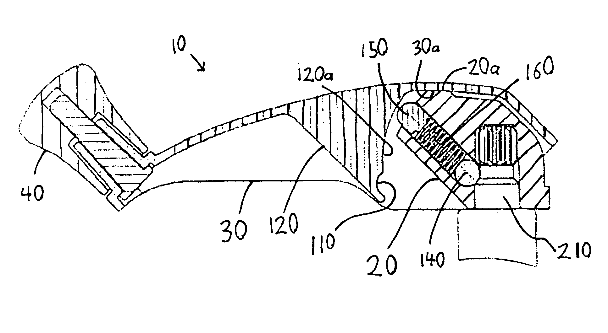
[0025]FIGS. 1-5 illustrate a window assembly 14 with a window handle 10 according to an embodiment of the present invention. As shown in FIG. 5, the window handle 10 mounts to a window actuator 12 of the window assembly 14. Selective rotation of the window handle 10 rotates a driveshaft 210 (FIG. 1) of the window actuator 12, which, in turn, opens or closes a window 16 of the window assembly 14. The window actuator 12 may comprise any suitable window actuator, as would be understood by those of ordinary skill in the art.

[0026] As shown in FIG. 1, the window handle 10 includes a base 20, an arm 30, and a knob 40. For convenience, directions (e.g., up, down, etc.) are defined relative to the views illustrated in FIGS. 1 and 2. However, depending on how the handle 10 is mounted to a particular window actuator 12 and window 14, the upper part of the handle 10 as viewed in FIGS. 1 and 2 may extend horizontally (e.g., if the handle is mounted to a vertical surface of a window frame).

[00...


PUM


Abstract

A window handle is configured to be manually snapped onto a driveshaft of a window actuator of a window. A locking structure securely attaches the handle to the driveshaft to prevent the handle from being pulled off of the driveshaft. The window handle is a folding handle that includes an arm that pivots relative to a base between closed and operable positions. A detent mechanism releasably holds the arm in its open position. A compression spring provides operational biasing force to both the detent mechanism and the locking structure. The arm and base include mating protrusions and bores that fit together to define a pivotal connection between the arm and the base.

Description

BACKGROUND OF THE INVENTION [0001] 1. Field of the Invention [0002] This invention relates to handles for window actuators. [0003] 2. Description of Related Art [0004] It is well known to provide a window (e.g., a casement window) with a window actuator that relies on rotation of an attached handle to open and close the window. Such window actuators and window handles are described in, for example, U.S. Pat. Nos. 5,168,770, 5,560,082, and 6,164,156. [0005] The rotating handle projects outwardly from the window frame. To make the handle more compact when it is not being used to open or close a window, it is known to provide a folding handle that pivots toward the window. Conventional examples of such folding handles are described in the above-noted patents. [0006] Conventional mechanisms that attach window handles to window actuators and / or conventional mechanisms that facilitate the folding of window handles are frequently complex and require numerous parts. SUMMARY OF THE INVENTION...

Claims


Application Information

Patent Timeline
Patent Type & Authority Applications(United States)
IPC IPC(8): G05G1/00
CPCE05B1/0092Y10T74/20744E05F11/10
Inventor GILL, BRYAN
Owner ARMADA TOOLWORKS
Learn More