Pegboard bracket assembly

a technology for pegboards and brackets, applied in the field of support brackets, can solve the problems of not having an existing pegboard display holder for products or promotional information, and achieve the effects of convenient adjustment, convenient manipulation and installation, and convenient securemen

Inactive Publication Date: 2006-11-23
MAGID EDWARD
View PDF11 Cites 18 Cited by
  • Summary
  • Abstract
  • Description
  • Claims
  • Application Information

AI Technical Summary

Benefits of technology

[0008] Another object of the present invention is to provide a pegboard display holder that is easy to manipulate and install onto existing pegboard display panels without need to remove product and promotional items already on display.
[0009] Still another object of the present invention is to provide a pegboard display holder that is easy to adjust in its extended length and readily secured in its mounted position on the pegboard panel.
[0010] A still further object of the present invention is to provide an adjustable and lockable pegboard display holder that is relatively inexpensive to fabricate and assemble, strong and sturdy in its assembled state, and reliable in its performance.

Problems solved by technology

Despite these known prior art devices, however, no existing pegboard display holder for product or promotional information is available having both a variable length adjustment feature and the capability of being locked in position, not only in its adjusted length but also in its mounted placement.

Method used


Image

  • Pegboard bracket assembly
  • Pegboard bracket assembly
  • Pegboard bracket assembly

Examples


Embodiment Construction

[0019] The following is a detailed description of a preferred embodiment of the present invention and the best presently contemplated mode of its production and practice. This description is further made for the purpose of illustrating the general principles of the invention but should not be taken in a limiting sense, the scope of the invention being best determined by reference to appended claims.

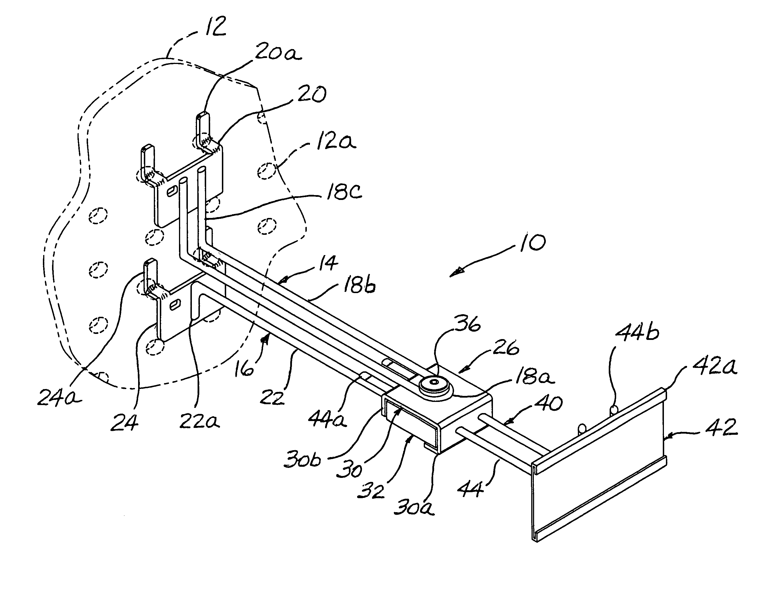
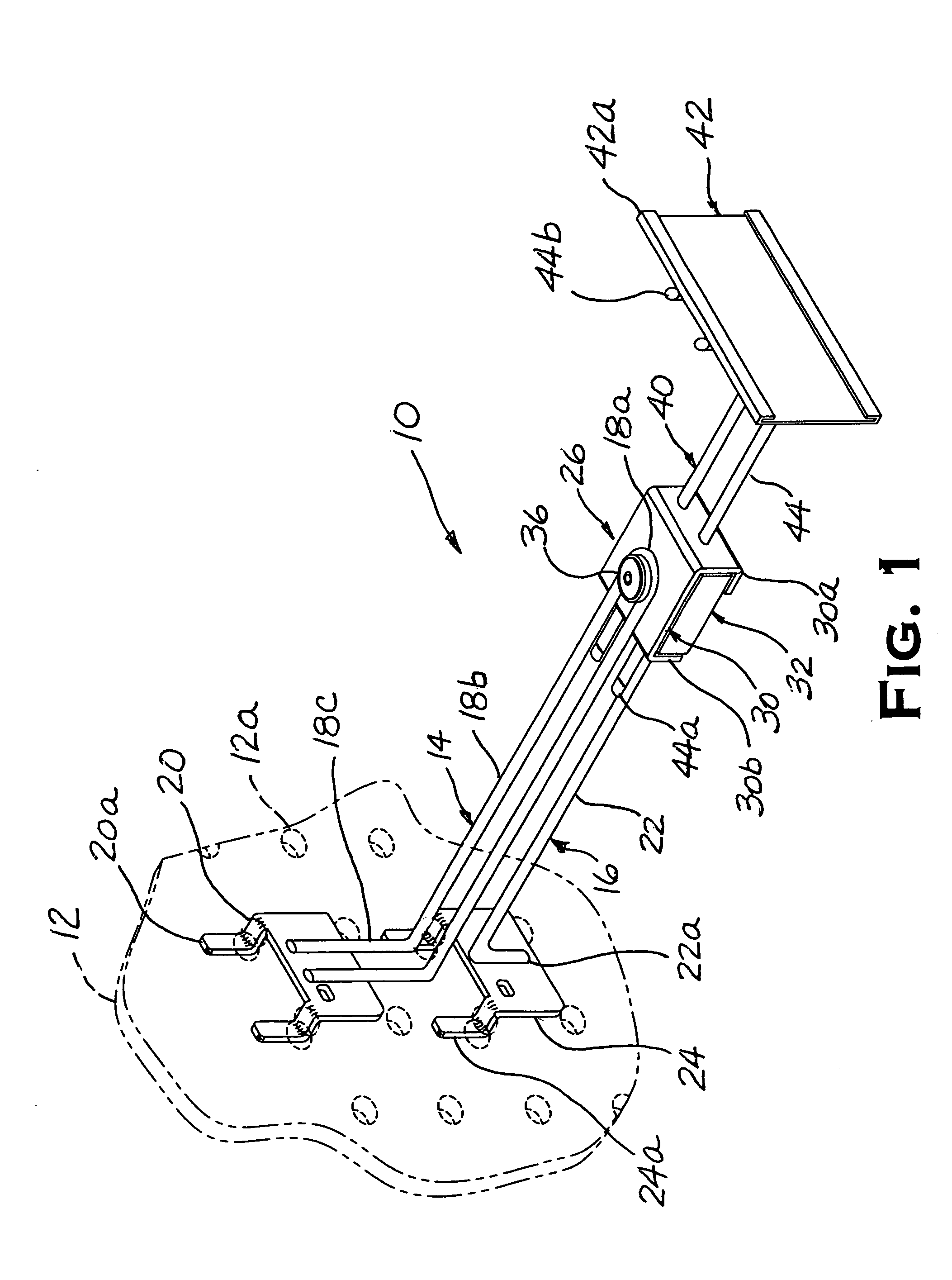
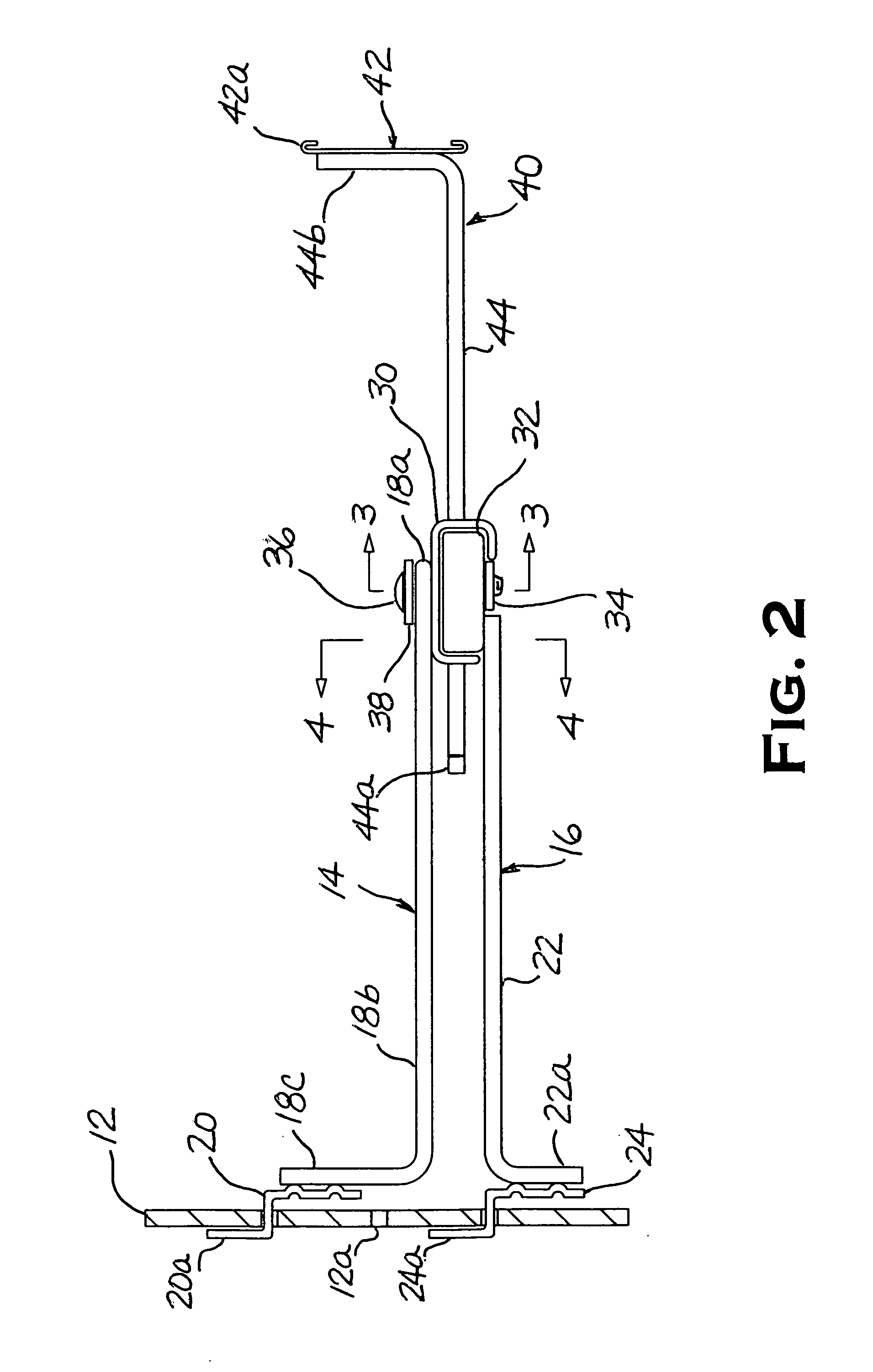
[0020] Referring now to the drawing figures and particularly to FIGS. 1 and 2, a bracket assembly made in accordance with the present invention and generally designated 10 is shown in mounted installation upon a conventional pegboard panel 12 (shown in phantom section) commonly used in retail merchandising displays. In its mounted installation, the present bracket assembly 10 is intended to engage selected holes 12a generally found in a matrix arrangement of horizontal rows and vertical columns on the pegboard panel 12 by means of a pair of pronged clips 20 and 24 that are attached at re...


PUM


Abstract

An improved bracket assembly is specially fabricated and adapted for mounted installation upon a conventional pegboard panel or like support surface to hold products and promotional materials in merchandising displays. The present bracket assembly comprises upper and lower clip arm members rearwardly directed in a bifurcated manner with each clip arm member having respective pronged clips for separate aligned engagement with the pegboard panel, an extendable channel strip arm member forwardly disposed having a channel strip segment attached thereto, and a junction box assembly intermediately positioned and adapted to engage the respective arm members and lock them in their respective position on the pegboard panel. The junction box assembly includes an upper box cover and lower box base formed to fit in a substantially closed configuration and adapted to be clamped together by a locking screw vertically disposed therethrough. The box cover is formed having lateral surfaces with aligned holes for sliding engagement of the channel strip arm and the base formed having transverse ribs embossed along its bottom surface to urge upon the channel strip arm when the junction box is clamped. The locking screw further engages a loop section formed in the upper clip arm member at the top of the junction box to retain the upper clip member and lock it in mounted position upon the pegboard panel.

Description

CROSS-REFERENCE TO RELATED APPLICATION [0001] This application is a continuation-in-part of Provisional Application Ser. No. 60 / 681,849 filed May 17, 2005 for Pegboard Bracket Assembly.BACKGROUND OF THE INVENTION [0002] The present invention relates to support brackets used to hold retail merchandise and their promotions in connection with pegboard support panels, and more particularly to an improved pegboard bracket assembly that is adjustable in its extended length and adapted to lock in place to prevent removal and theft. [0003] In retail merchandising, store displays are often constructed using an upright pegboard panel that provides a vertically oriented support surface upon which support brackets are mounted to hold products and point-of-purchase promotions. Typically, the pegboard panel has a matrix of uniformly spaced holes that are arranged in horizontal rows and vertical columns. The pegboard holes are formed through the panel thickness to support stationary mounting of th...

Claims


Application Information

Patent Timeline
Patent Type & Authority Applications(United States)
IPC IPC(8): A47F5/08
CPCA47F5/0823
Inventor MAGID, EDWARD
Owner MAGID EDWARD
Why Eureka
Try Eureka