
Linkage for rimmed ammunition

a technology of rimmed ammunition and linkage structure, which is applied in the field of linkage structure for rimmed ammunition, can solve the problems of difficult linkage and lack of effective structure for linking these rimmed cartridges, and achieve the effects of convenient assembly and manipulation, easy removal of ammunition, and convenient deploymen

Active Publication Date: 2013-01-01
MAGPUL INDUSTRIES
View PDF11 Cites 19 Cited by
  • Summary
  • Abstract
  • Description
  • Claims
  • Application Information

AI Technical Summary

Benefits of technology

[0006]In view of the foregoing disadvantages inherent in the known types of linking systems for rimmed ammunition, this invention provides a more efficient linkage system for rimmed ammunition cartridges and also a delinking system for removing and chambering the ammunition. As such, the present invention's general purpose is to provide a new and improved linkage system that is easy to assemble and manipulate and also easily deployed and features easy removal of ammunition from the individual links.

Problems solved by technology

However, rimmed ammunition, where the bottom rim extends beyond the circumference of the cartridge jacket, has notoriously been difficult to link, and there is no effective structure that links these rimmed cartridges in a push-through feeding system.

Method used


Image

  • Linkage for rimmed ammunition
  • Linkage for rimmed ammunition
  • Linkage for rimmed ammunition

Examples


Embodiment Construction

[0032]With reference now to the drawings, the preferred embodiment of the linkage assembly and the associate delinking apparatus is herein described. It should be noted that the articles “a”, “an”, and “the”, as used in this specification, include plural referents unless the content clearly dictates otherwise.

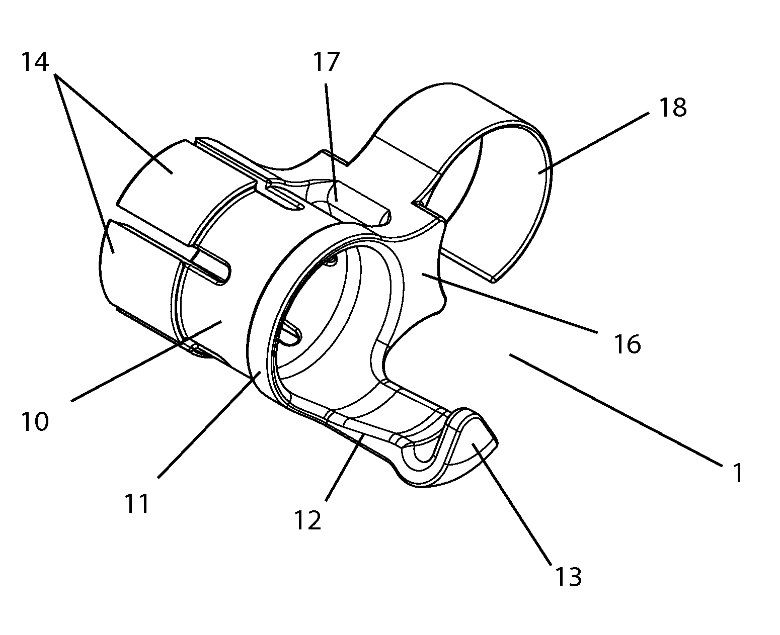
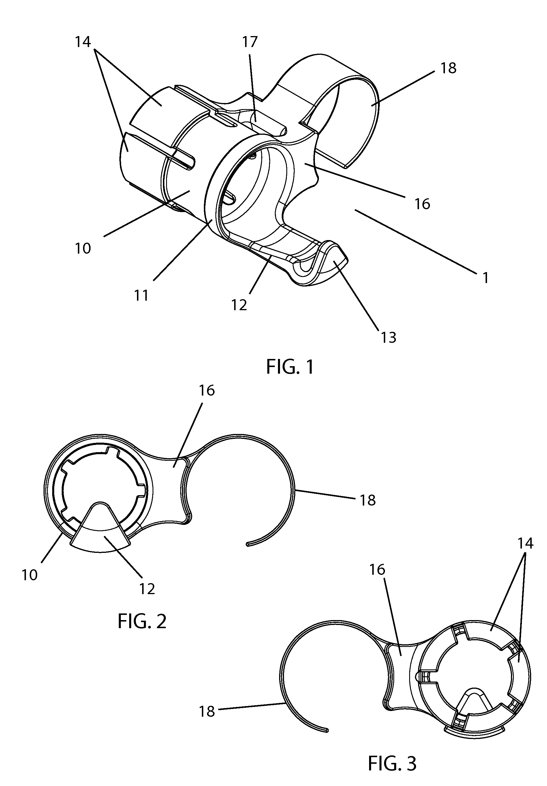
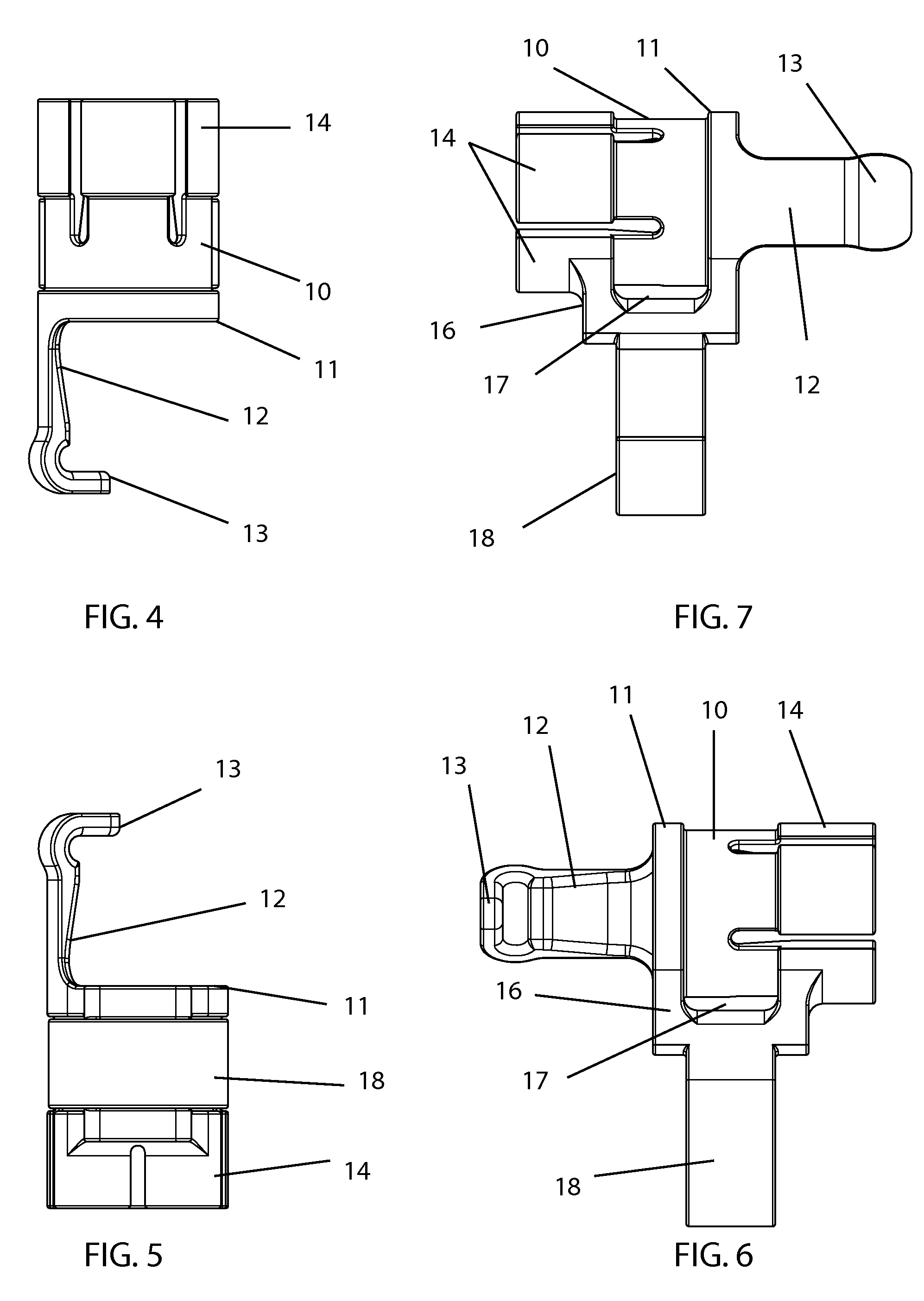
[0033]With reference to FIGS. 1-17 a preferred embodiment of the link 1 is described. In the preferred embodiment, the basic link structure 1 is a cylindrical collar 10 sized to encompass a cartridge of ammunition of a given type. A first, securement, arm 12 extends from a rim 11 of the cylindrical collar 10 and terminates in a clip 13. This first arm aids in securing the link 1 to the cartridge of ammunition 19 by clipping onto the rim 19a of the cartridge. A spacer 16 projects from a side of the cylindrical collar 10 and a second, linking, arm 18 projects therefrom. The linking arm 18 is arcuate and wraps around a cylindrical collar 10 of an adjacent link, as shown in FIGS. 1...


PUM


Abstract

A linking system for rimmed ammunition is disclosed. The linking system features individual links that each encompass one ammunition cartridge while having an arcuate lateral arm which encompasses a neighboring link and associated cartridge. A plurality of collet arms secure the cartridge and separate as the cartridge is forced forward in the delinking process. Angular momenta from the feeding motion and the rotational motion of the de-linking assembly combine to rotate a first link away and apart from the next associated link.

Description

CROSS-REFERENCES TO RELATED APPLICATIONS[0001]This Application claims priority based on U.S. Provisional Application Ser. No. 61 / 361,000, filed Jul. 2, 2010 and incorporates the same in its entirety by reference herein.FIELD OF THE INVENTION[0002]The present invention relates to the field of firearms and more particularly relates to a linkage structure for rimmed ammunition and a push-through de-linking system for separating ammunition linked with the linkage structure.BACKGROUND OF THE INVENTION[0003]Linked ammunition is commonly used in machine guns where ammunition is chain fed into the weapon, de-linked and fired. However, rimmed ammunition, where the bottom rim extends beyond the circumference of the cartridge jacket, has notoriously been difficult to link, and there is no effective structure that links these rimmed cartridges in a push-through feeding system. In linked ammunition systems, the linkages typically rely on adjacent ammunition cartridges to hold the links together....

Claims


Application Information

Patent Timeline
Patent Type & Authority Patents(United States)
IPC IPC(8): F41A9/29
CPCF41A9/29
Inventor ABBOTT, BRIAN F.
Owner MAGPUL INDUSTRIES
Learn More