Timer display device having light generating module with circular arrangement

a technology light generating module, which is applied in the direction of visual indication, instruments, horology, etc., can solve the problems of timer display device being unable to display accurate and producing rus

Active Publication Date: 2006-11-23
EPISTAR CORP
View PDF5 Cites 8 Cited by
  • Summary
  • Abstract
  • Description
  • Claims
  • Application Information

AI Technical Summary

Benefits of technology

[0007] Therefore, it is a primary object to provide a timer display device. The timer display device comprises a counting unit and at least twelve light generating modules with circular arrangement to be hour positions. The counting unit is a clock for counting an actual time. The light generating module is to incorporate the counting unit for adjusting a light generating status in order to display the actual time correspondingly. The light generating module further comprises a red light component, a green light component, and a blue light component. The light generating status of the light generating module is composed of the brightness of the red light component, the brightness of the green light component, and the brightness of the blue light component. The brightness of the red light component is to display the hour of the actual time correspondingly. The brightness of the green light component is to display the minute of the actual time correspondingly. The brightness of the blue light is to display the second of the actual time correspondingly. Accordingly, by providing a timer display device having light generating modules with circular arrangement, problems in conventional timer display devices can be resolved that users could perceive the actual time easily by adjusting of the light generating status of light generating modules

Problems solved by technology

However, the above timer display device is usually machinery that is easy to produce rust due to oxidation.
Consequently, the timer display device is unable to display the accurate time that users must adjust the timer display device frequently for displaying the accurate time.

Method used


Image

  • Timer display device having light generating module with circular arrangement
  • Timer display device having light generating module with circular arrangement
  • Timer display device having light generating module with circular arrangement

Examples


Embodiment Construction

[0016] To make it easier for our examiner to understand the objective of the invention, its innovative features and performance, a detailed description and technical characteristics of the present invention are described together with the drawings as follows.

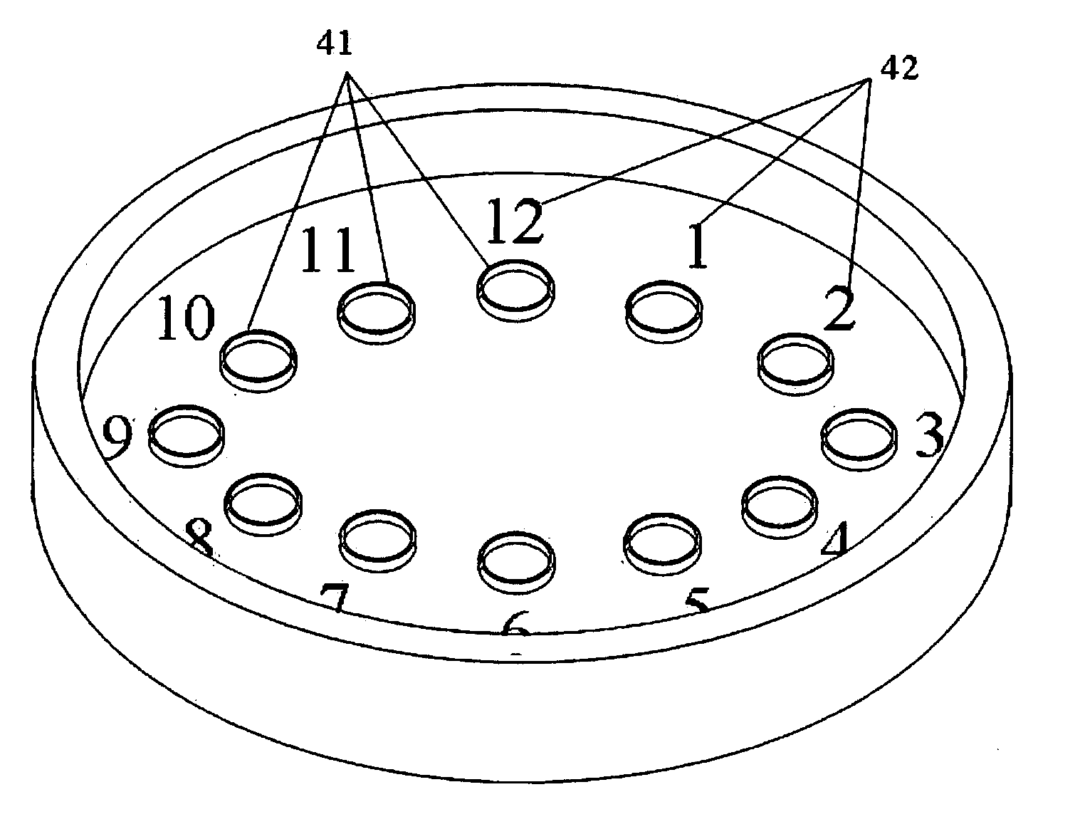
[0017] Referring to FIG. 4, a block diagram of an example of a timer display device is illustrated. The timer display device comprises a counting unit and at least twelve light generating modules 41 with circular arrangement to hour position, wherein the hour position indicates ciphers of “1, 2, . . . , 12”. The timer display device further comprises twelve timing symbols 42 that arranges in circular to be hour positions in order to take the light generating module 41 to display the hour position. The counting unit is a clock for counting an actual time. The light generating module 41 is to incorporate the counting unit to adjust a light generating status of the light generating module in order to display the actual time corres...


PUM


Abstract

This utility discloses a timer display device for displaying time. The timer display device comprises a counting unit and at least twelve light generating modules with circular arrangement to hour positions. The counting unit is a clock for counting actual time. The light generating module is used to modify light generating status according to the counting unit to display actual time correspondingly.

Description

FIELD OF THE INVENTION [0001] This utility generally relates to a timer display device, more particularly relates to a timer display device having light generating modules with circular arrangement. BACKGROUND OF THE INVENTION [0002] Time display usually includes clocks and watches for displaying an accurate time. Referring to FIG. 1, a block diagram of a conventional timer display device is illustrated. The timer display device comprises an hour hand 11, a minute hand 12, a second hand 13, and a plurality of time symbols 14 that arrange in circular to an hour position. Three sides of the hour hand 11, the minute hand 12, and the second hand 13 are fixed on the center of the timer display device that rotates through the mechanical movement to indicate the plurality of time symbols 14 for displaying an actual time. The hour hand 11 is used for displaying the hour of the actual time correspondingly. The minute hand 12 is used for displaying the minute of the actual time correspondingl...

Claims


Application Information

Patent Timeline
Patent Type & Authority Applications(United States)
IPC IPC(8): G04C17/00G04B25/00G04B19/30G04G9/02
CPCG04G9/04
Inventor SU, HWA
Owner EPISTAR CORP
Why Eureka
Try Eureka