Modeling low frame rate videos with bayesian estimation

a low frame rate video and video model technology, applied in image analysis, instruments, computing, etc., can solve the problems of difficult computer vision task of inability to use conventional object tracking methods, and difficulty in tracking objects in videos, so as to improve the effect of object tracking

Inactive Publication Date: 2006-11-23
MITSUBISHI ELECTRIC RES LAB INC
View PDF5 Cites 36 Cited by
  • Summary
  • Abstract
  • Description
  • Claims
  • Application Information

AI Technical Summary

Benefits of technology

[0021] When a stationary camera is used, an accurate scene model can improve object tracking. Therefore, the invention provides a method for modeling a dynamic scene from a low frame rate video acquired of the scene.

Problems solved by technology

Hence, conventional object tracking methods cannot be used.
Tracking objects in a video, especially a video acquired at a low frame rate, is a difficult computer vision task.

Method used


Image

  • Modeling low frame rate videos with bayesian estimation
  • Modeling low frame rate videos with bayesian estimation
  • Modeling low frame rate videos with bayesian estimation

Examples


Embodiment Construction

[0027] Method Overview

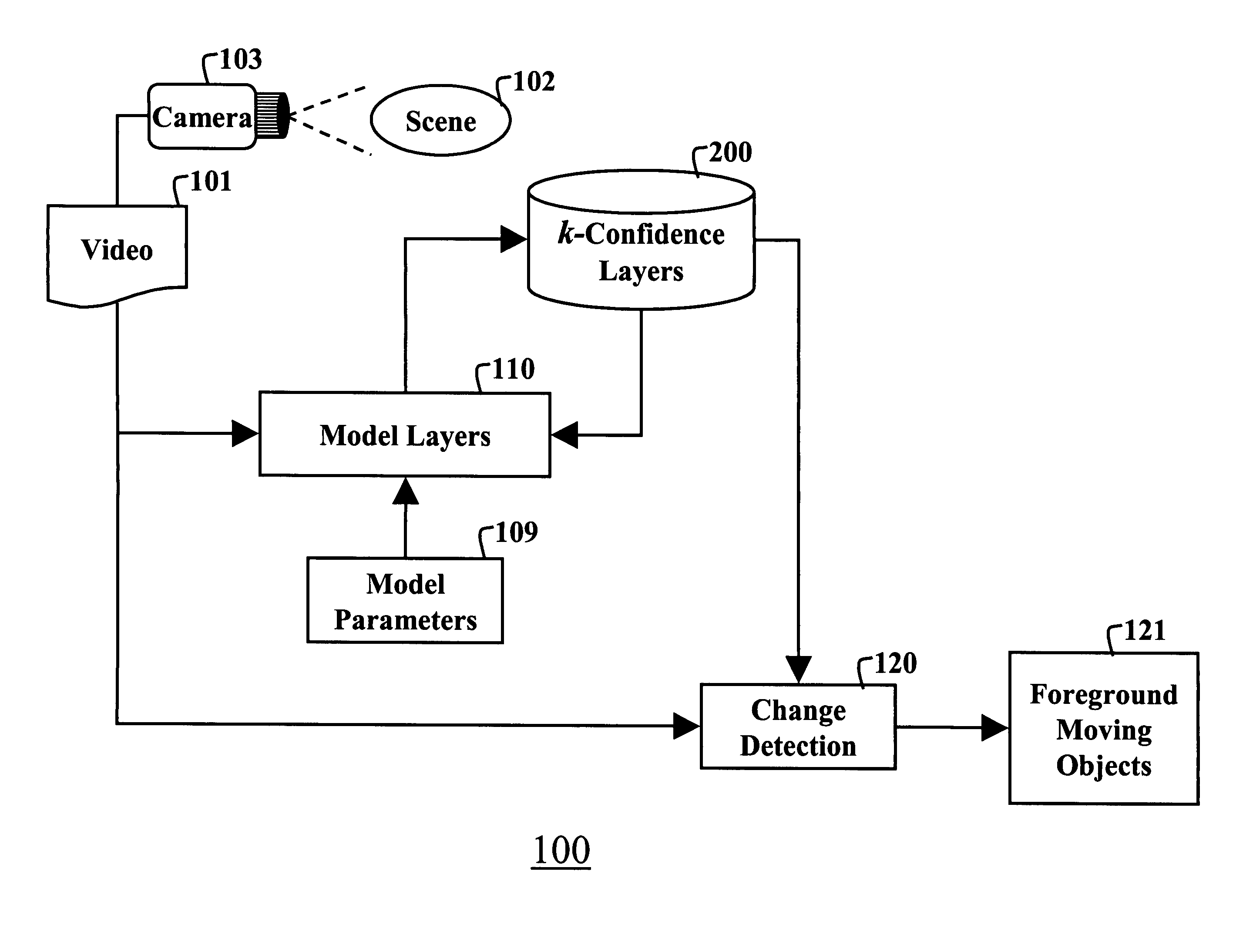
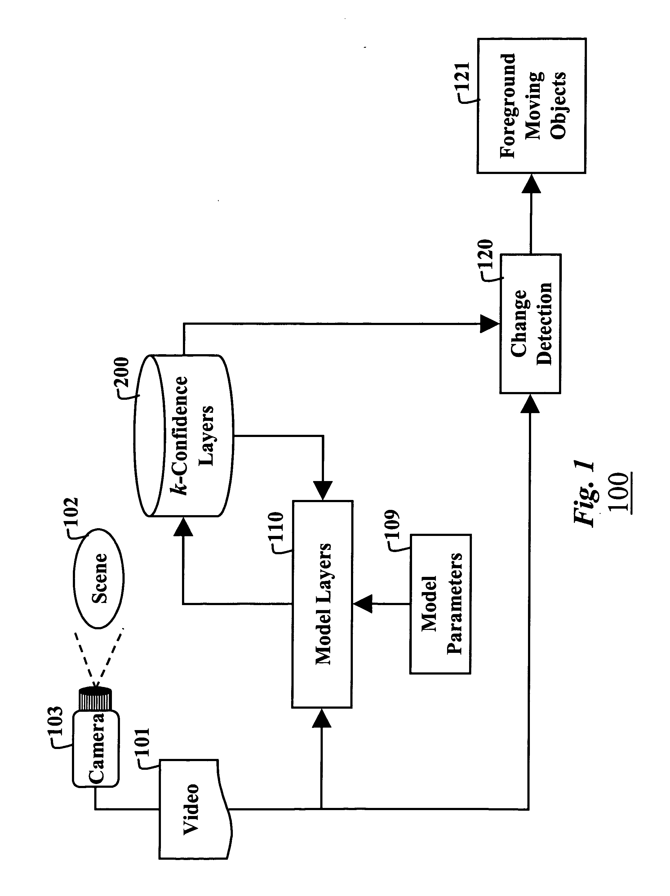
[0028]FIG. 1 shows a method 100 according to our invention for modeling a scene 102 in order to detect moving objects in the scene. A video 101 is acquired of the scene 102 with a camera 103. For each pixel in each frame of the video, the scene is modeled 110 by multiple layers 200 of 3D multivariate Gaussian distributions according to model parameters 109. Each layer corresponds to a different appearance, i.e., color intensity, of the pixel over time. We perform our operations in a red, green, and blue (RGB) color space. Changes in the layers of the scene model are determined to detect 120 moving objects 121 in the scene. The detailed steps of the method are shown in FIG. 3, described below.

[0029] Model Layers

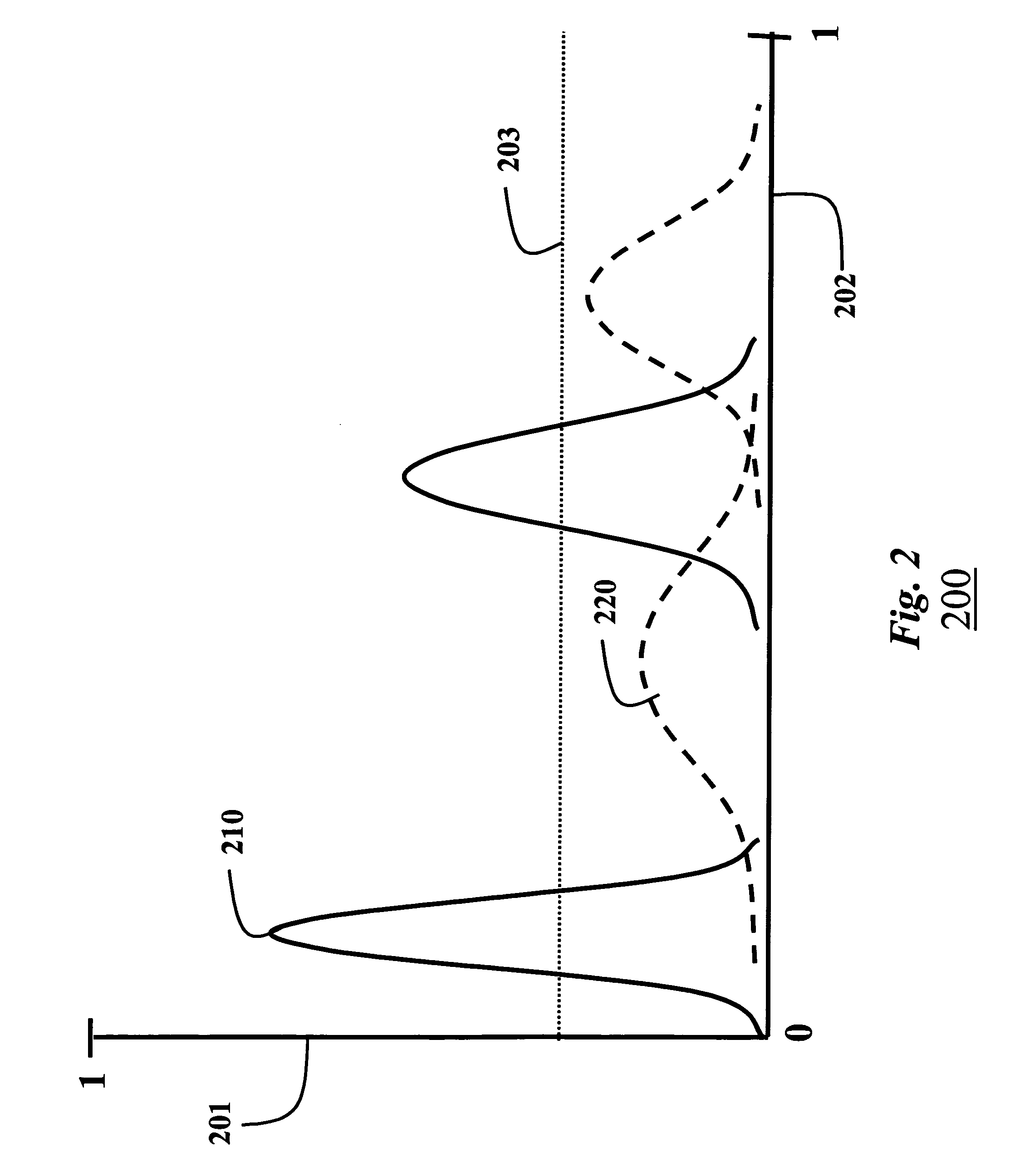
[0030]FIG. 2 is a simplified schematic of the multiple layers 200 of the model according to our invention. A vertical axis 201 indicates a confidence score, and a horizontal axis 202 a pixel color value, both normalized to a range [0, 1]. If a layer is...


PUM


Abstract

A video is acquired of a scene. Each pixel in each frame of the video is represented by multiple of layers. Each layer includes multiple Gaussian distributions. Each Gaussian distribution includes a mean and a covariance. The covariance is an inverse Wishart distribution. Then, the layers are updated for each frame with a recursive Bayesian estimation process to construct a model of the scene. The model can be used to detect foreground and background pixels according to confidence scores of the layers.

Description

FIELD OF THE INVENTION [0001] This invention relates generally to computer vision and modeling scenes, and more particularly to tracking objects in videos acquired of scenes at low frame rates. BACKGROUND OF THE INVENTION [0002] One fundamental task in many computer vision applications segments foreground and background regions in a sequence of frames, i.e., a video, acquired of a scene. The segmentation is useful for higher-level operations, such as tracking moving objects. [0003] One way to detect a region of “moving” pixels in a video is to first acquire a reference frame of a static scene. Then, subsequent frames acquired of the scene are subtracted from the reference frame, on a pixel-by-pixel basis, to segment the video into difference images. The intensity values in the difference images can be thresholded to detect the regions of moving pixels that are likely associated with moving objects in the scene. [0004] Although this task appears fairly simple, in real world applicati...

Claims


Application Information

Patent Timeline
Patent Type & Authority Applications(United States)
IPC IPC(8): G06K9/00G06K9/62G06V10/24
CPCG06K9/00711G06T7/208G06K9/32G06T7/277G06V20/40G06V10/24
Inventor TUZEL, ONCELPORIKLI, FATIH M.
Owner MITSUBISHI ELECTRIC RES LAB INC
Why Eureka
Try Eureka