Eureka AIR delivers breakthrough ideas for toughest innovation challenges, trusted by R&D personnel around the world.

Spring launched needle safety clip

Active Publication Date: 2006-11-23
B BRAUN MELSUNGEN AG
View PDF67 Cites 46 Cited by
  • Summary
  • Abstract
  • Description
  • Claims
  • Application Information

AI Technical Summary

Benefits of technology

[0011] According to the present invention, there is provided a hypodermic needle assembly designed such that the action of compressing the plunger of the syringe automatically activates a resilient, member-loaded needle shield such that the needle shield moves into position to block the needle tip, such that there is no risk of accidental injury and infection from an exposed needle and there is no need for the activation of any additional mechanisms to complete the needle shielding process.
[0013] A needle guard activator assembly is provided for urging the needle tip safety guard in a distal direction along the needle. The activator assembly comprises a pressure trigger and a resilient member, wherein the pressure trigger is mounted in the needle hub and is arranged between the syringe plunger when the syringe tip is in the syringe tip engagement chamber and the needle tip safety guard, such that when the syringe plunger is translated distally, the plunger pin mechanically interacts with the pressure trigger. The pressure trigger is configured to transmit the force of the plunger pin longitudinally along the axis of the needle assembly in a distal direction, such that the resilient member is activated to urge the needle tip safety guard distally along the needle and over the needle tip to its blocking position. The needle tip safety guard is passively actuated so that the user is not required to perform any operations outside of those employed using conventional hypodermic needles. In order to use the safety hypodermic needle assembly, it is not necessary for the user to learn additional procedures. The needle tip safety guard automatically blocks the needle tip so that the user, or those who dispose of the used needle, are not subjected to inadvertent needle sticks.

Problems solved by technology

Most of these needle guards are cumbersome and interfere with a single-handed procedure, and or require additional complicated pieces to attach the needle guard to the needle tip.
However, all of these designs have undesirable features which make them unsuitable for many applications.
However, while this mechanism provides for preventing the needle shield from disengaging and moving back down the length of the needle, the needle shields are only frictionally engaged to the tip of the needle, such that it is possible to slip the needle shield off of the distal end of the needle leaving the needle tip exposed.
In addition, this design requires the user to manually activate the spring mechanism, which adds to the complexity of the design, manufacture, and use of the hypodermic needle assembly.
However, the needle shields utilizing this design still require the user to manually activate a second mechanism that then engages the needle guard, adding to the complexity of the design, manufacture and use of the hypodermic needle assembly.
However, the needle guards provided in most of these prior art designs consist of a simple hollow sleeve having an open distal end.
While this design does provide protection from most inadvertent contact with the needle tip, it is still possible with such designs for a user to accidentally or purposefully insert a finger into the open distal end of the needle guard sleeve and thus come into contact with the contaminated needle tip.
However, these manually activated designs require that the user either slide or apply the needle shield to the tip of the needle by hand, significantly raising the risk of unintentional contact with the needle tip.
However, as noted above, the known solutions suffer from at least one serious drawback.

Method used


Image

  • Spring launched needle safety clip
  • Spring launched needle safety clip
  • Spring launched needle safety clip

Examples


Embodiment Construction

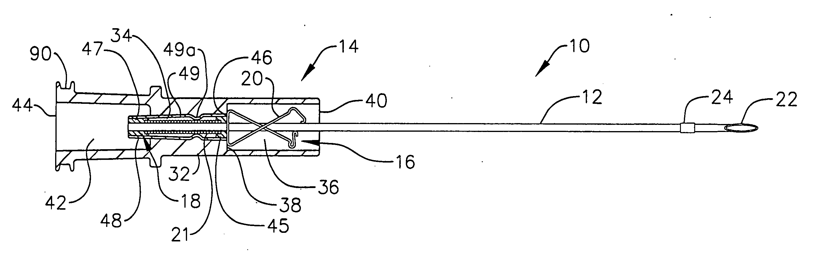
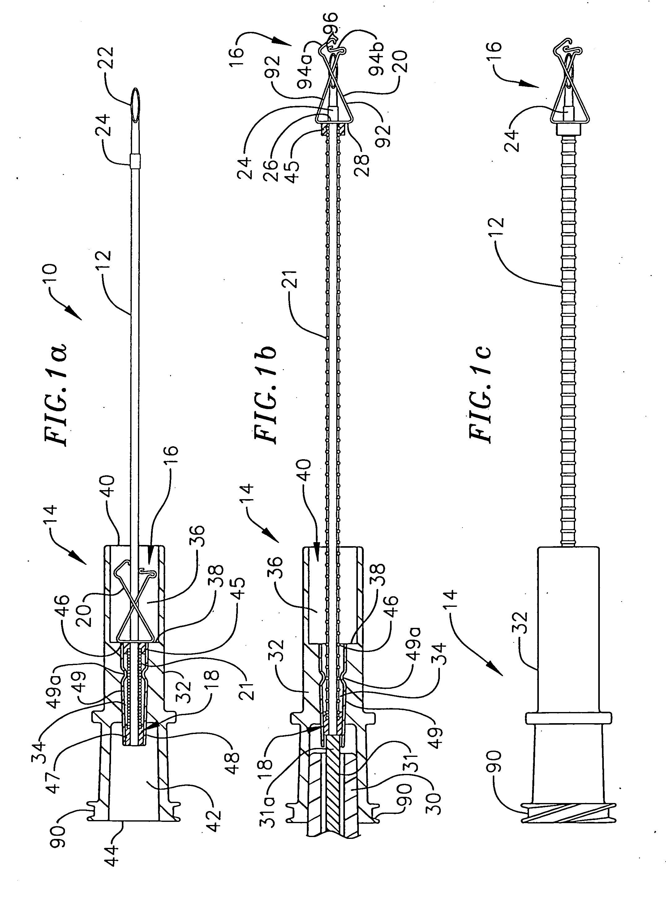
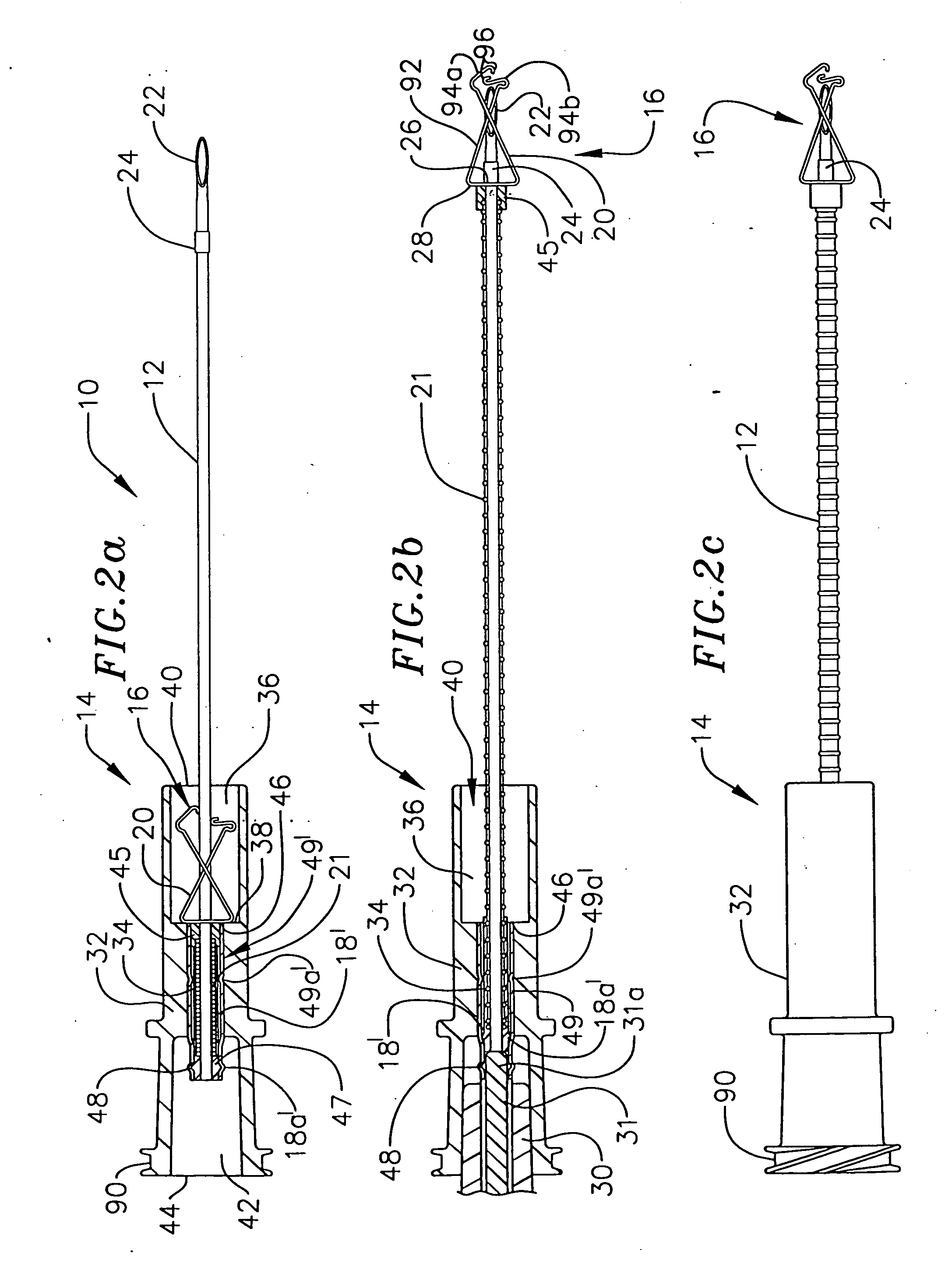
[0072] The present invention is directed to a hypodermic needle assembly designed such that the movement of the needle shield into position to block the needle tip occurs as a direct consequence of the depression of a syringe plunger while injecting a medicant into a patient. The detailed description set forth below in connection with the appended drawings is intended as a description of the presently preferred embodiments of the hypodermic needle assembly provided in accordance with the present invention and is not intended to represent the only forms in which the present invention may be constructed or utilized. The description sets forth the features and the steps for constructing and using the hypodermic needle assembly of the present invention in connection with the illustrated embodiments. It is to be understood, however, that the same or equivalent functions and structures may be accomplished by different embodiments that are also intended to be encompassed within the spirit ...


PUM


Abstract

A hypodermic needle assembly configured such that the movement of a needle shield into position to block the needle tip occurs as a direct consequence of a longitudinal force applied by insertion of a syringe plunger is provided. The hypodermic needle assembly according to the present invention comprises a needle, a needle hub, and a safety spring clip assembly, the safety spring clip assembly being configured to automatically launch from the needle hub and slide along the needle until the spring clip meets a needle stop at the needle tip, thus preventing the guard from being removed from the needle shaft. A method of using the hypodermic needle assembly according to the present invention is also provided, which includes the method of launching the spring clip with a syringe having multiple advancing mechanisms.

Description

CROSS-REFERENCE TO RELATED APPLICATIONS [0001] This is a divisional application of Ser. No. 10 / 251,735, filed Sep. 20, 2002, which is a continuation-in-part of application Ser. No. 09 / 965,055 entitled “Spring Launched Needle Safety Clip” filed Sep. 26, 2001, now U.S. Pat. No. 6,623,458, the contents of each related applications are expressly incorporated herein by reference.[0002] Hypodermic needle assemblies are discussed herein which include a needle assembly having a resilient member for launching a safety clip device to block the tip of a disposable needle after use to facilitate the safe handling of such needles. Syringes with distinct mechanisms for dispensing medication and for launching the safety clip are also discussed. BACKGROUND [0003] Medical care of individuals requires the widespread use of needles for taking blood samples, intravenous drug delivery, and the introduction or removal of other fluids via cannula, needles, or syringes. In the current context, the use of h...

Claims


Application Information

Patent Timeline
IPC IPC(8): A61M5/00A61M5/32A61M5/315
CPCA61M5/326A61M5/3273Y10S128/919A61M2005/325A61M2005/31516A61M5/3275
Inventor WOEHR, KEVINFREIGANG, HELMUTFUCHS, JUERGENREUTER, JUERGENSIEMON, KLAUSWENDE, JOERGHILBERG, FRANK
Owner B BRAUN MELSUNGEN AG
Why Eureka
Eureka Blog
Learn More