Safety syringe system

a safety syringe and syringe technology, applied in the field of safety syringe systems, can solve the problems of not being able to identify particularly contaminated used syringes, lack of solid locking means, increasing the potential contamination risk simply by covering the needle, etc., to achieve reliable operation, effective use, and low cost

Inactive Publication Date: 2003-02-06
DEHARDE LAWRENCE G +1
View PDF0 Cites 60 Cited by
  • Summary
  • Abstract
  • Description
  • Claims
  • Application Information

AI Technical Summary

Benefits of technology

0028] The present invention provides a safety syringe system which is effective in use, reliabl...

Problems solved by technology

Often, the distraction surrounding a medical emergency or like situation may result in used syringes not being identified as being particularly contaminated.
This could result in the re-use of the syringe by a medical professional and potential contamination resulting therefrom.
Additionally, if the syringe is not properly disposed of an addict may thereafter utilize it to administer illegal drugs to himself and others, spreading the virus, bacteria, disease, or anything else which may be present on the point and shaft of the hollow metal needle.
U.S. Pat. No. 4,702,738 attempts to address the problem of inadvertent pricks, but lacks a solid locking means as the system would appear to be locked solely by spring force, which could be overcome.
U.S. Pat. No. 4,725,267 addresses the problem of inadvertent pricks by covering the point of the needle, but activating it requires the operator to work in the area of the point of the needle, increasing the potential contamination risk simply to cover the needle.
Further, the cover could be forced back exposing the needle, pot...

Method used


Image

  • Safety syringe system
  • Safety syringe system
  • Safety syringe system

Examples


third embodiment

[0073] Continuing with FIGS. 6A and 6B, the present invention extends the activation tab and provides a cam 57 or taper on the tip so as to communicate with the thumb flange on the syringe plunger upon fully depressing the plunger so that, upon the administering of a fluid to a patient via the syringe, the plunger is depressed 59 to a point where the thumb flange 59' engages the flange 57, directing 60 the activation tab 56 to the triggering slot 61 so that the spring 62 within the housing 63 is able to then urge 64 the cover 65 over the needle tip.

fourth embodiment

[0074] FIG. 7 illustrates the present invention, where the plunger thumb flange 70 has a built-in cam 71 configured to engage the activation tab 72 to urge 73 the activation tab to the triggering slot 74 upon administering 75 the plunger.

[0075] FIGS. 10A-10B illustrate another variation of the self-actuating syringe concept, wherein the plunger flange 92 has emanating therefrom a angled activation member 93, configured to engage a cam 95 emanating from the activation piece 94 to urge 97 the activation piece for triggered activation 98' with the pressing 98 of the plunger, allowing bias to urge 99 the protective cover over the needle tip.

[0076] FIGS. 8A-8B and 9A-9B illustrate a fifth alternative embodiment of the present invention, wherein the housing 82 does not utilize a spring bias to drive the activation piece 83, instead relying upon manual activation by the user wherein the housing has formed therethrough a longitudinal slot 81 along its length to accommodate the passage of an...


PUM


Abstract

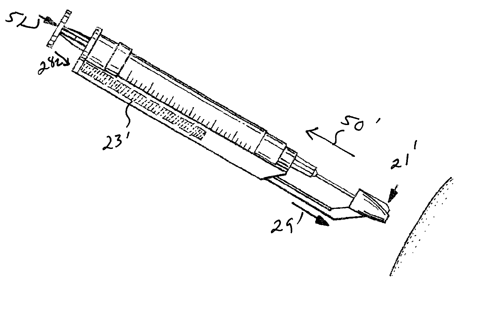
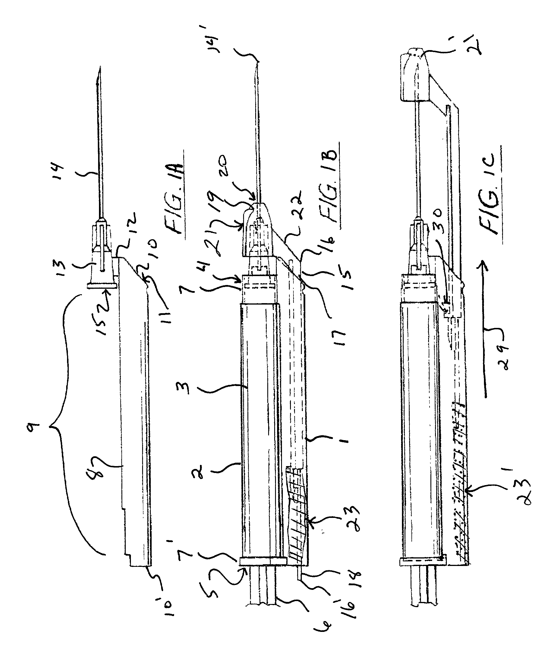
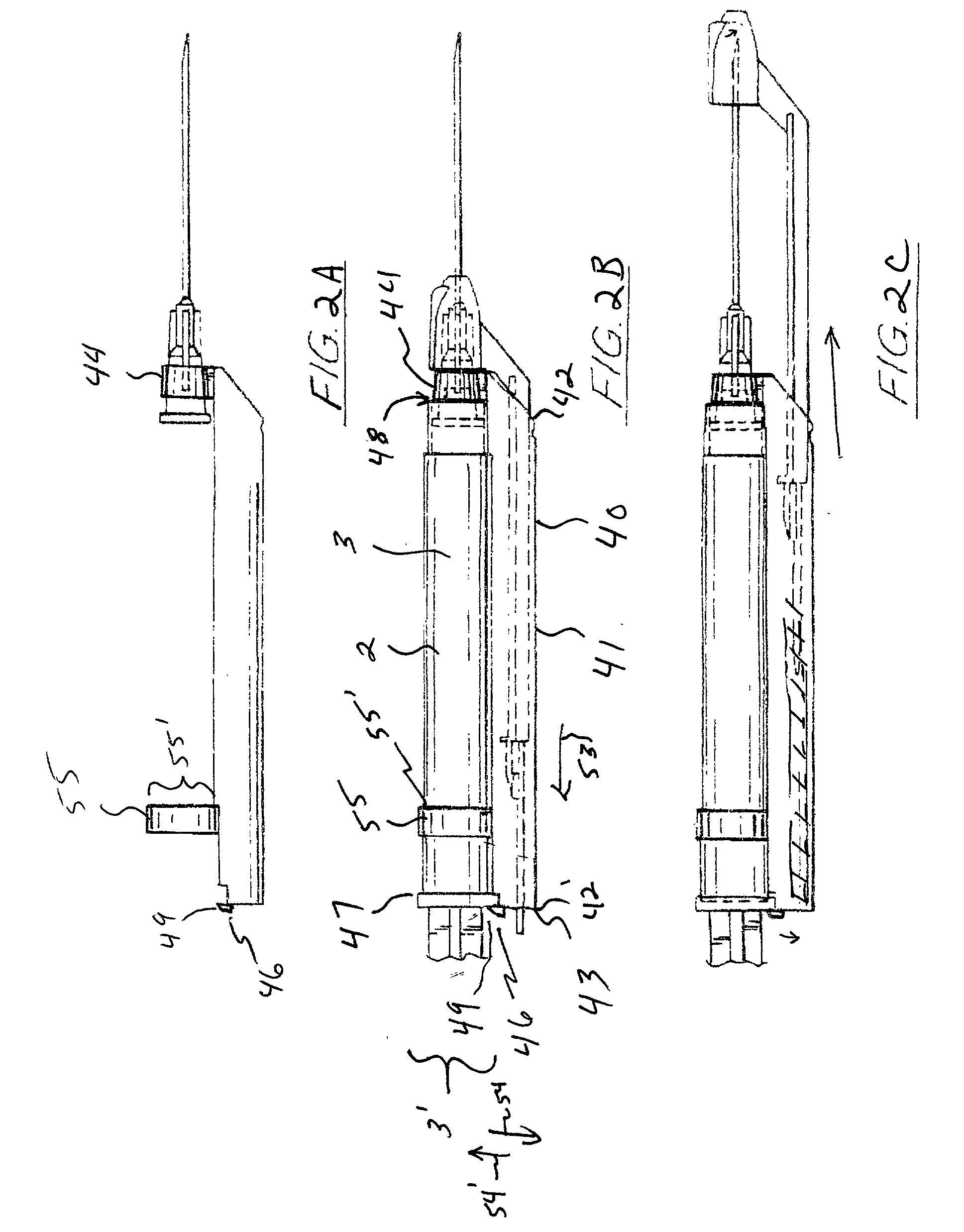
A system for converting an off-the-shelf syringe into a safety syringe for preventing accidental needle stick or infection. The preferred embodiment of the present invention is configured to mount to an off-the-shelf syringe via threaded, snap, permanent, or other engagement to the cannula hub of the syringe, wherein the device may include the needle for mounting to the syringe, or via barrel rings configured to mount about the barrel of the syringe. The device is configured to convert the syringe into a safety syringe including a protective cover in longitudinal communication with the syringe needle, the protective cover configured to longitudinally envelope the base of the needle in a storage position, and engage and cap the needle tip in a protected configuration after the instrument has been utilized.

Description

TECHNICAL FIELD of the INVENTION[0001] The present invention relates to systems for preventing infection from unsterile hypodermic needles or the like, and more particularly to a system for preventing needle stick or re-use of unsterile hypodermic needles or like items.[0002] The preferred embodiment of the present invention teaches a system for converting an off-the-shelf syringe into a safety syringe for preventing accidental needle stick or infection. The preferred embodiment is configured to mount to an off-the-shelf syringe via threaded, snap on, adhesive, permanent, or other engagement to the collar of the syringe, wherein the device may include the needle with a hub for mounting to the syringe, or in an alternative embodiment, via barrel rings configured to mount about the barrel of the syringe.[0003] The device is configured to convert the syringe into a safety syringe including a protective cover in longitudinal communication with the syringe needle, the protective cover co...

Claims


Application Information

Patent Timeline
IPC IPC(8): A61M5/32
CPCA61M5/3257A61M5/326A61M5/3269
Inventor DEHARDE, LAWRENCE G.DEHARDE, MICHAEL H.
Owner DEHARDE LAWRENCE G
Why Eureka
Try Eureka