
Needle safety deflection device

a deflection device and needle technology, applied in the direction of intravenous devices, catheters, needles used for infusion, etc., can solve the problems of increased risk of hiv transmission, increased risk of needle stick injury, and devices that require manipulation or disassembly after use, etc., to achieve the effect of reducing the risk of infection

Active Publication Date: 2009-11-26
BECTON DICKINSON & CO
View PDF19 Cites 53 Cited by
  • Summary
  • Abstract
  • Description
  • Claims
  • Application Information

AI Technical Summary

Benefits of technology

The present invention provides a safety device for intravenous catheter assemblies that overcomes the shortcomings of current safety devices. The invention includes a housing with a hollow interior region and a biasing member that applies a force to a needle to secure its end. The needle may be a blood vessel piercing needle or a needle used to access a catheter. The invention also includes a lock feature to maintain the position of the biasing member and secure the end of the needle. The technical effects of the invention include improved safety and ease of use for intravenous catheter assemblies.

Problems solved by technology

Needle stick injuries may arise during planned use and exposure, and / or as a result of carelessly or maliciously discarded needles.
Of particular concern, however, are injuries from hollow-bore needles, especially those used for blood collection or intravenous (“IV”) catheter insertion.
These devices are likely to contain residual blood and are associated with an increased risk for HIV transmission.
Additionally, devices that require manipulation or disassembly after use, such as hollow-bore needles used for IV catheter insertion, have rates of injury over five times that for disposable hypodermic syringes.
This process of physically manipulating and disassembling the needle and catheter after the catheter has been properly positioned creates substantial risks of accidental needle sticks and exposure to blood and blood-borne pathogens.

Method used


Image

  • Needle safety deflection device
  • Needle safety deflection device
  • Needle safety deflection device

Examples


Embodiment Construction

[0032]The illustrated embodiments of the present invention will be best understood by reference to the drawings, wherein like parts are designated by like numerals throughout. It will be readily understood that the components of the present invention, as generally described and illustrated in the Figures herein, may be arranged and designed in a wide variety of different configurations. Thus, the following more detailed description, as presented in the Figures, is not intended to limit the scope of the invention as claimed, but is merely representative of selected embodiments of the invention. The following description is intended only by way of example, and simply illustrates certain selected embodiments of devices, systems, and processes that are consistent with the invention as claimed herein.

[0033]As used in this specification, the term “needle” refers to any of various devices that may be used to pierce the skin to acquire intravenous access, such as a hypodermic needle, a holl...


PUM


Abstract

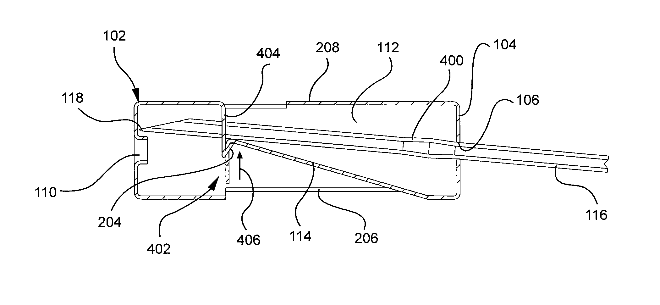
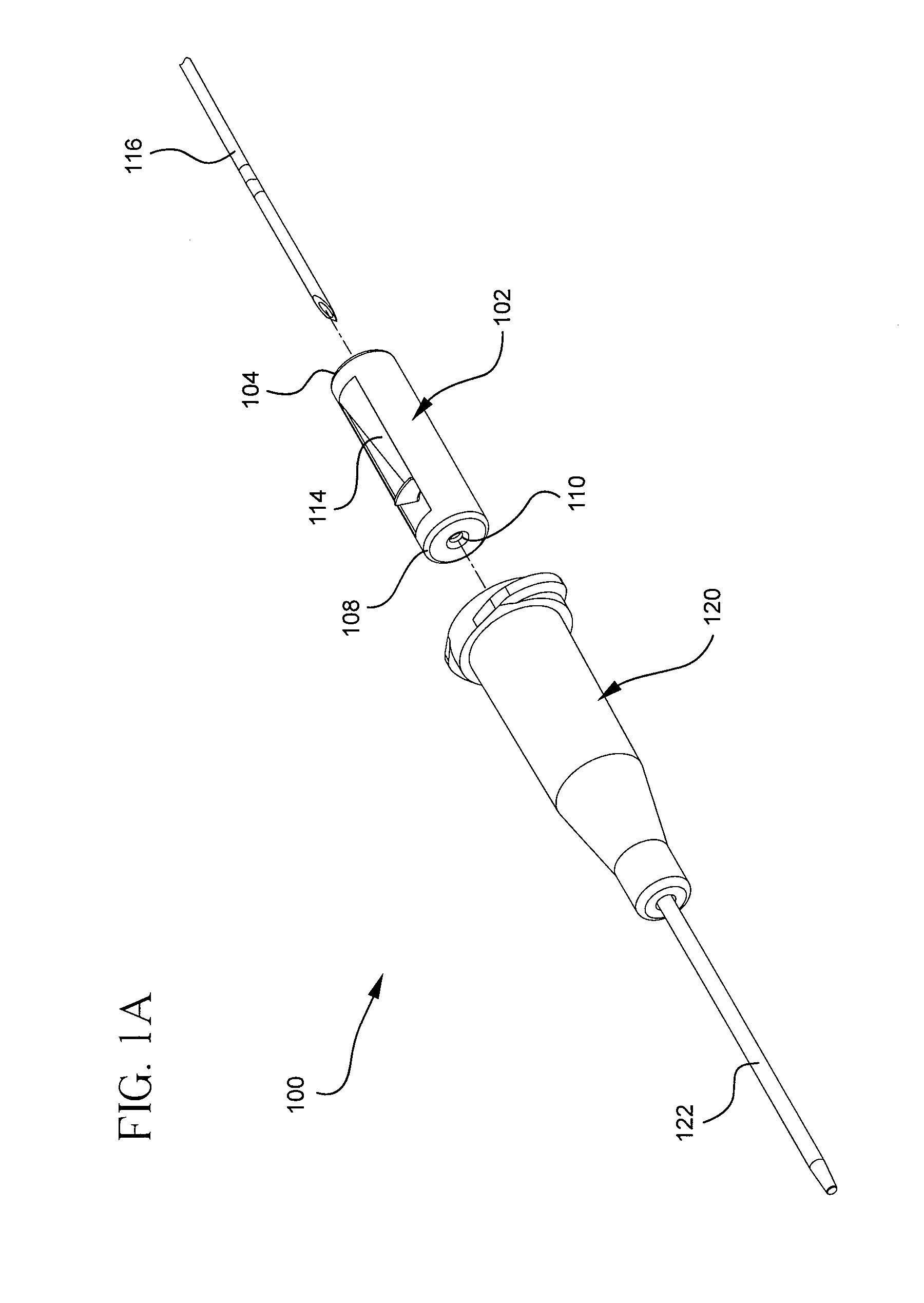
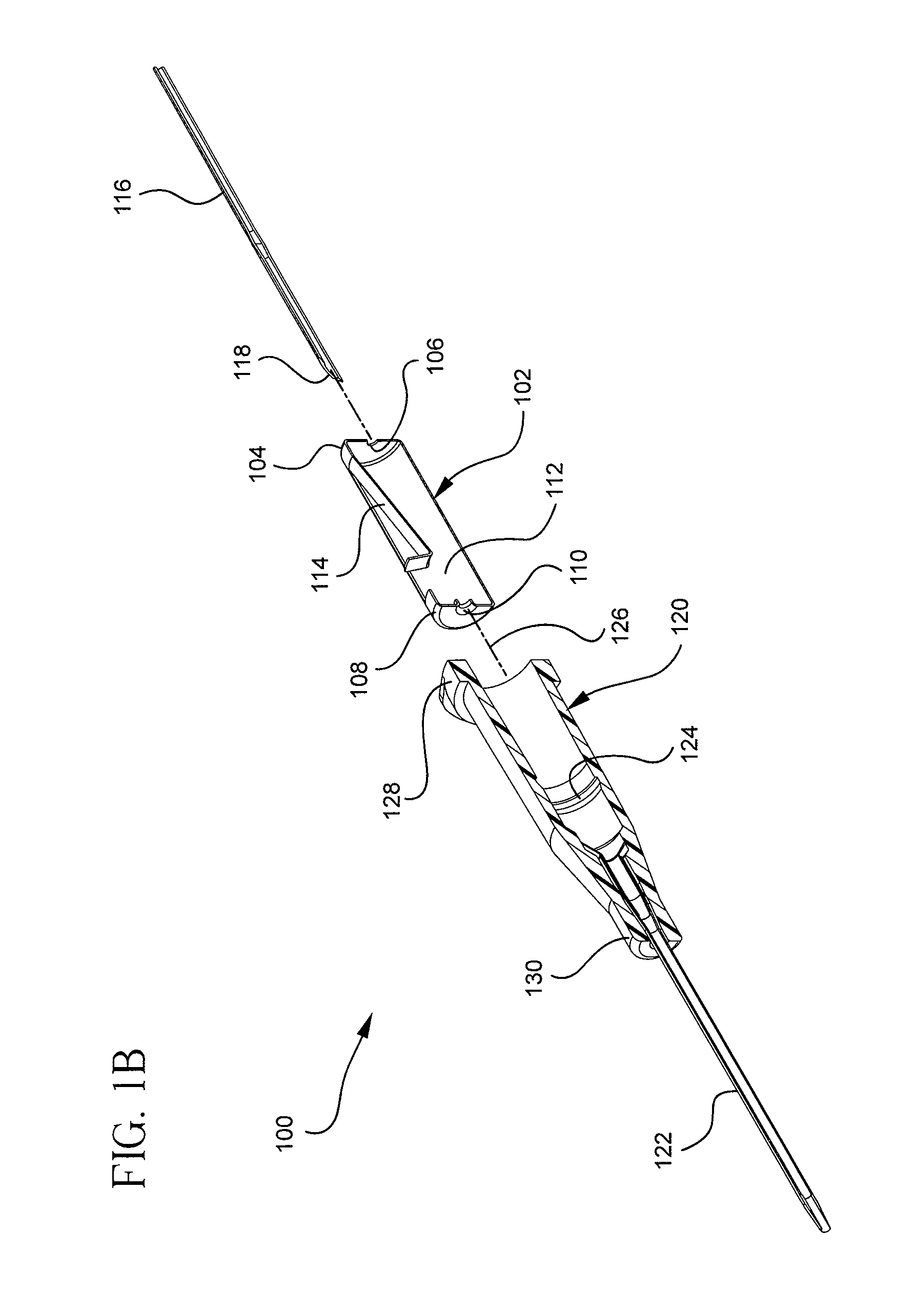
An apparatus to automatically secure an end of a needle after contact with a blood vessel. The apparatus may include a housing and a biasing member, where the housing includes a hollow interior region extending between a proximal end and a distal end thereof. A proximal opening may be integrated into the proximal end, while a distal opening may be integrated into the distal end. The proximal and distal openings may be configured to receive a needle therethrough along a longitudinal axis. The biasing member may be coupled to the housing and configured to apply a force to the needle. The force may be oriented to displace the needle relative to the longitudinal axis upon retracting an end of the needle through the distal opening into the hollow interior region. Embodiments of the present invention may thus secure the end of the needle within the hollow interior region after use to prevent accidental needle sticks and exposure to blood and blood-borne pathogens.

Description

BACKGROUND OF THE INVENTION[0001]Hypodermic needles are notorious for spreading blood-borne diseases such as Hepatitis B, Hepatitis C, and Human Immunodeficiency Virus (“HIV”), the virus that causes Autoimmune Deficiency Syndrome (“AIDS”). Health care workers are among those most at risk for contracting such diseases, as hypodermic needles are commonly used in medical fields. Needle stick injuries may arise during planned use and exposure, and / or as a result of carelessly or maliciously discarded needles.[0002]The Federal Needle Stick Safety Act was enacted into law on Nov. 6, 2000, and is aimed at reducing the risk to health care workers arising from accidental needle sticks. Among other compliance mandates, the Federal Needle Stick Safety Act requires the use of needles with engineered needle injury protections. Accordingly, many hypodermic needles manufactured today include a needle tip shield or the like to protect against accidental needle sticks.[0003]Of particular concern, ho...

Claims


Application Information

Patent Timeline
Patent Type & Authority Applications(United States)
IPC IPC(8): A61M5/50
CPCA61M5/3273A61M2005/3249A61M25/0618
Inventor HARDING, WESTON F.MCKINNON, AUSTIN JASONSUWITO, WANPETERSON, BART D.
Owner BECTON DICKINSON & CO
Learn More