Cable retention system

a technology of cable retention and cable, which is applied in the direction of hose connection, flexible element, packaging, etc., can solve the problems of reducing the flow rate of liquid or gas carried by the conduit, affecting the performance of the equipment being fed by the cable, and significant damage to the cable or the cable being secured

Inactive Publication Date: 2006-11-30
DT SEARCH & DESIGNS
View PDF19 Cites 17 Cited by
  • Summary
  • Abstract
  • Description
  • Claims
  • Application Information

AI Technical Summary

Benefits of technology

[0015] It is therefore an object of the present invention to provide a cable tie which is less likely to bind the cable or cables being secured as a result of both a unique locking mechanism and a surface construction which will be somewhat yielding to the pressure of the cable against it.
[0018] An important aim of this invention is to provide a cable tie which provides a margin of error against being tightened too tight, the margin of error being in the form of an inner surface which is somewhat yielding and therefore avoids binding the cable even if tightened beyond what is necessary.
[0021] Still another object of this invention is to provide a cable tie which provides for positive engagement of the locking mechanism which can be felt by the user of the device so that he or she will know positive engagement has been obtained.

Problems solved by technology

The disadvantages of the prior art devices described above are several, First, and foremost, with many types of cable, especially low voltage computer cables, the cable is sensitive to binding and it is frequently the case that the cable tie is tightened too tightly so that it adversely affects the performance of the equipment being fed by the cable.
If an uncoated wire is utilized as the tie, significant damage to the cable or cables being secured may result.
Their lumens may become narrowed or partially occluded if a cable tie is overtightened, diminishing the rate of flow of liquids or gases carried by the conduits.
Another disadvantage of the prior art, even when utilizing the more popular plastic cable ties described above, is that there is no way to judge when the tie is properly secured.
Since there is no margin for error, the tie may be too tight and may adversely affect performance without the knowledge of the installer who applied the tie.
Another disadvantage of prior art ties is that for the most part, once they are tightened, they cannot be released without use of a cutting tool, which destroys the tie.
Another disadvantage of prior art ties is that, even when installed properly so as not to bind the cable during normal use, if the cable is bent around a corner there is the possibility of the cable becoming pinched and adversely affected, even though this was not the case when the cable was laid out in a straight line.

Method used


Image

  • Cable retention system
  • Cable retention system
  • Cable retention system

Examples


Embodiment Construction

[0034] As required, detailed embodiments of the present invention are disclosed herein; however, it is to be understood that the disclosed embodiments are merely exemplary of the invention, which may be embodied in various forms. Therefore, specific structural and functional details disclosed herein are not to be interpreted as limiting, but merely as a basis for the claims and as a representative basis for teaching one skilled in the art to variously employ the present invention in virtually any appropriately detailed structure.

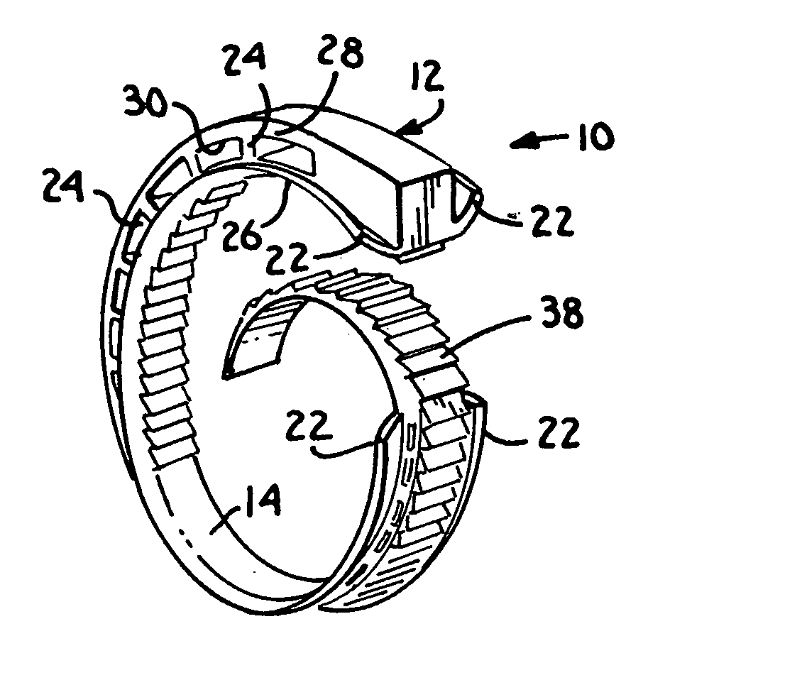
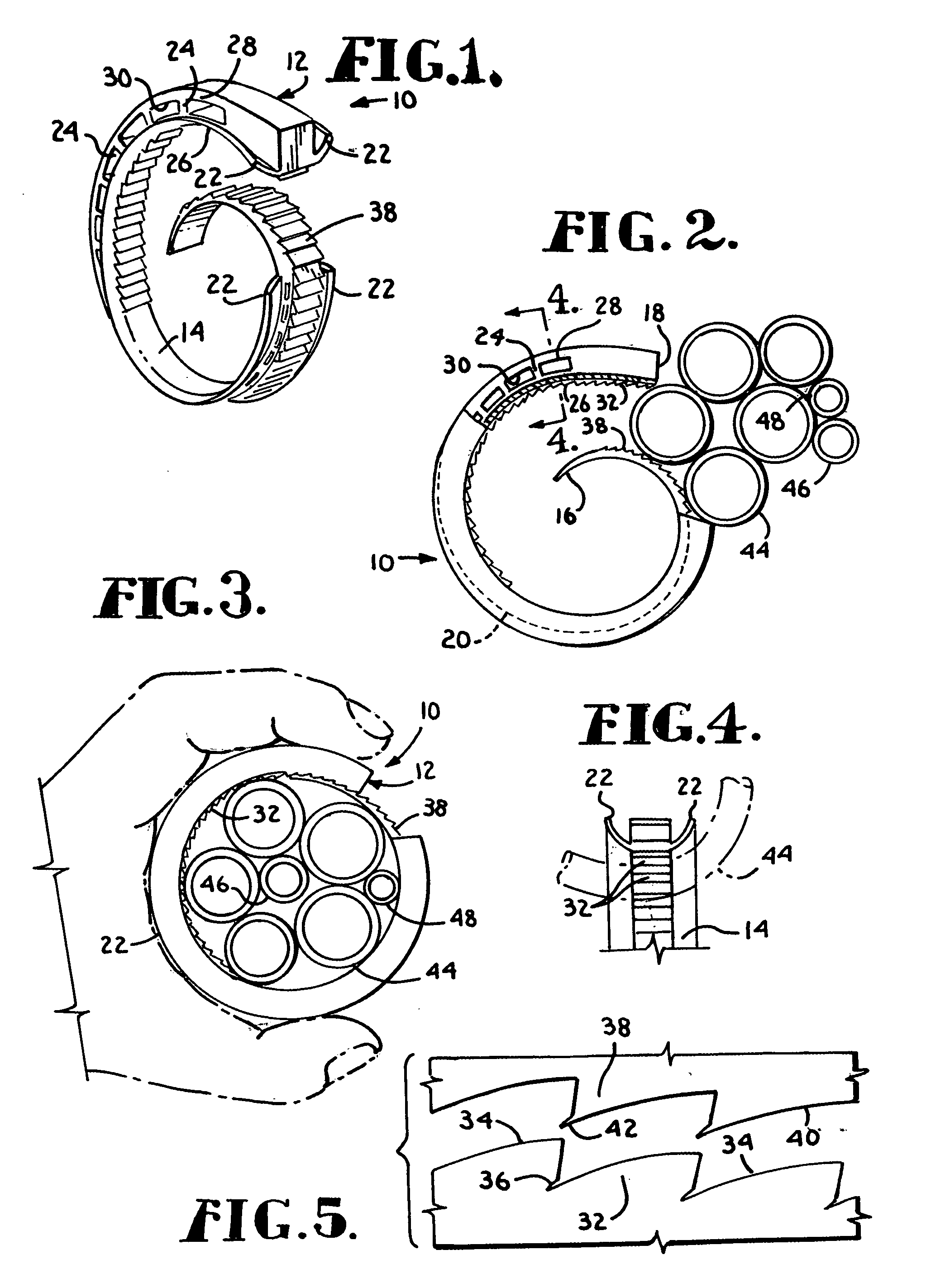
[0035] Referring initially to FIG. 1, the cable tie according to the present invention is designated generally by the numeral 10. Cable tie 10 comprises an annular support 12 of generally rectangular cross section and a generally convex inner face 14, which is integrally formed with annular support 12 around its circumference. The cross sectional area of the support 12 decreases significantly from one end to the other. It is desirable that the cross section...


PUM


Abstract

A cable retention system includes a cable tie and a storage and installation tool. The cable tie includes an elongated band having head and tail ends. The inner surface of the band includes spaced grooves offset toward the tail end to render it more flexible than the head end. Teeth along the inner surface of the band adjacent the head end and along the outer surface of the band adjacent the tail end engage in a circumferential direction when the head end overlaps the tail end. The tool has an annular configuration with an elongated longitudinal opening and an inner raceway for receiving cables. The opening enables the tube to be slipped over a group of cables and moved along the cables. As the tube is moved along the cables, the ties are slipped off and onto the cables at selected spaced locations for securing the cables into a bundle.

Description

CROSS-REFERENCE TO RELATED APPLICATION [0001] This application is a continuation-in-part of U.S. patent application Ser. No. 10 / 359,867 entitled CABLE RETENTION DEVICE filed Feb. 7, 2003, which is based on Provisional Application Ser. No. 60 / 333,255,430 entitled CABLE RETENTION DEVICE filed on Feb. 8, 2002.BACKGROUND OF THE INVENTION [0002] This invention relates generally to retaining devices and, more particularly to a tie for securing one or more objects such as cables, wires or conduits in a bundle or to another object. [0003] Existing cable ties take several forms. The most elementary example is a wire which is either bare or is coated with insulation and which is twisted around one or more cables which it is desired to bundle together. A more popular cable tie which is now used is a preformed plastic strip having teeth which pass through a catch box, where the teeth engage a complemental restraint which locks the end of the tie in place. [0004] The disadvantages of the prior a...

Claims


Application Information

Patent Timeline
Patent Type & Authority Applications(United States)
IPC IPC(8): B65D63/00H02G3/30
CPCH02G3/30Y10T24/142Y10T24/44248Y10T24/153Y10T24/1498
Inventor THOMPSON, ALVIN DEANNURSKI, FRANK
Owner DT SEARCH & DESIGNS
Why Eureka
Try Eureka